 |
Remove the engine oil level dipstick.
OIL PUMP > REMOVAL |
| 1. REMOVE ENGINE ASSEMBLY WITH TRANSAXLE |
Remove the engine assembly with transaxle (Click here).
| 2. REMOVE ENGINE OIL LEVEL DIPSTICK GUIDE |
|
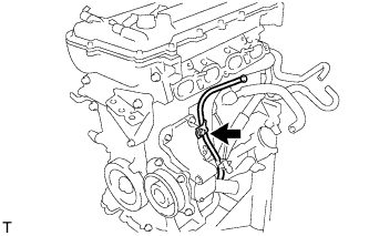
Remove the engine oil level dipstick.
Remove the bolt and dipstick guide.
Remove the O-ring from the dipstick guide.
| 3. DISCONNECT NO. 3 WATER BY-PASS HOSE |
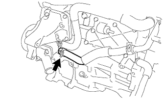 |
Disconnect the No. 3 water by-pass hose from the water inlet housing.
| 4. DISCONNECT WATER INLET HOSE |
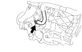 |
Disconnect the water inlet hose from the water inlet housing.
| 5. REMOVE WATER INLET |
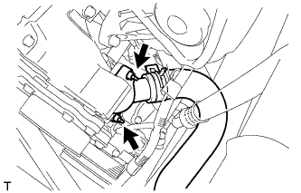 |
Remove the 2 nuts and disconnect the water inlet.
| 6. REMOVE THERMOSTAT |
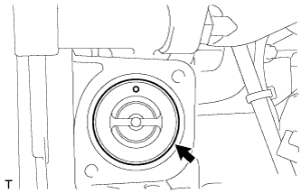 |
Remove the thermostat.
Remove the gasket from the thermostat.
| 7. REMOVE IGNITION COIL ASSEMBLY |
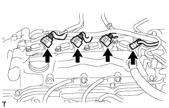 |
Disconnect the 4 ignition coil connectors.
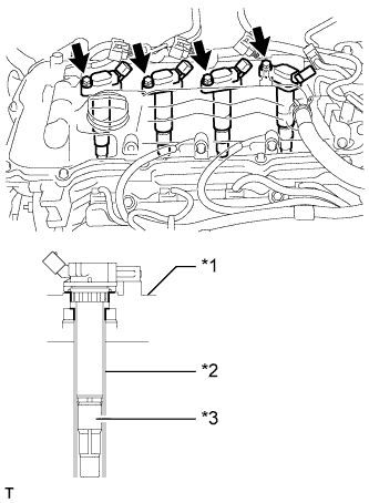 |
Remove the 4 bolts and 4 ignition coils.
| *1 | Cylinder Head Cover |
| *2 | Spark Plug Tube |
| *3 | Plug Cap |
| 8. REMOVE RADIO SETTING CONDENSER |
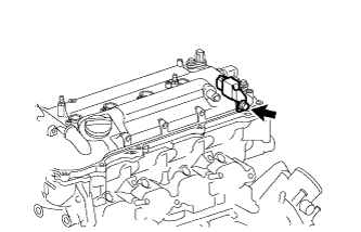 |
Remove the bolt and setting condenser.
| 9. REMOVE CYLINDER HEAD COVER SUB-ASSEMBLY |
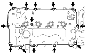 |
Remove the 13 bolts, seal washer and cylinder head cover.
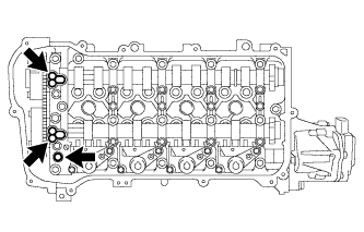 |
Remove the 3 gaskets from the camshaft bearing cap.
| 10. REMOVE CYLINDER HEAD COVER GASKET |
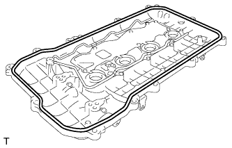 |
Remove the cylinder head cover gasket.
| 11. REMOVE SPARK PLUG TUBE GASKET |
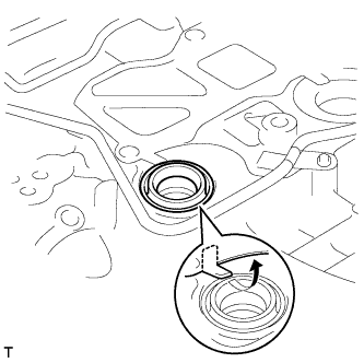 |
Pry up the 4 claws of the ventilation baffle plate.
Remove the 4 gaskets from the cylinder head cover.
| 12. SET NO. 1 CYLINDER TO TDC/COMPRESSION |
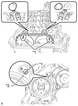 |
Turn the crankshaft pulley until its notch and timing mark "0" of the timing chain cover are aligned.
| *1 | Timing Mark |
| *2 | Timing Notch |
Check that timing marks on both the camshaft timing exhaust gear and camshaft timing gear are facing upward as shown in the illustration.
| 13. REMOVE CRANKSHAFT PULLEY |
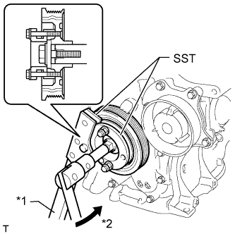 |
Using SST, hold the crankshaft pulley and loosen the pulley bolt. Further loosen the bolt until 2 or 3 threads are screwed into the crankshaft.
| *1 | Hold |
| *2 | Turn |
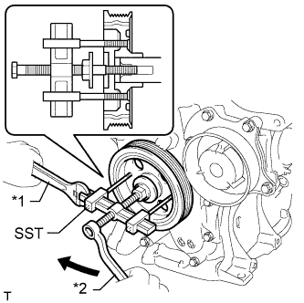 |
Using SST and the pulley bolt, remove the crankshaft pulley and pulley bolt.
| *1 | Hold |
| *2 | Turn |
| 14. REMOVE NO. 1 CHAIN TENSIONER ASSEMBLY |
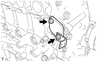 |
Remove the 2 nuts, bracket, chain tensioner and gasket.
| 15. REMOVE TIMING CHAIN COVER SUB-ASSEMBLY |
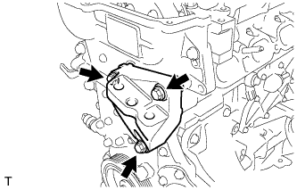 |
Remove the 3 bolts and engine mounting bracket.
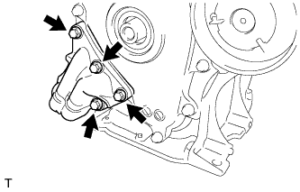 |
Remove the 4 bolts and oil filter bracket.
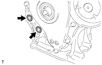 |
Remove the 2 O-rings.
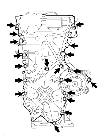 |
Remove the 19 bolts.
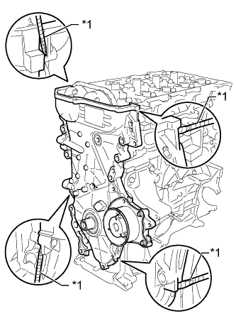 |
Remove the timing chain cover by prying between the timing chain cover and cylinder head, camshaft housing, cylinder block and stiffening crankcase with a screwdriver as shown in the illustration.
| *1 | Protective Tape |
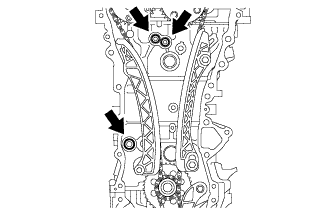 |
Remove the 3 O-rings.
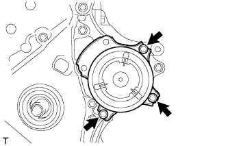 |
Remove the 3 bolts and water pump.
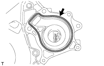 |
Remove the gasket.
| 16. REMOVE TIMING CHAIN COVER OIL SEAL |
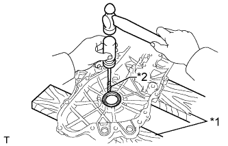 |
Place the timing chain cover on wooden blocks.
| *1 | Wooden Block |
| *2 | Protective Tape |
Using a screwdriver, tap out the oil seal.
| 17. REMOVE CHAIN TENSIONER SLIPPER |
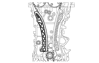 |
Remove the chain tensioner slipper from the cylinder block.
| 18. REMOVE NO. 1 CHAIN VIBRATION DAMPER |
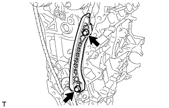 |
Remove the 2 bolts and chain vibration damper.
| 19. REMOVE CHAIN SUB-ASSEMBLY |
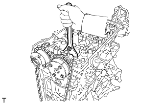 |
Hold the hexagonal portion of the camshaft with a wrench and turn the camshaft timing gear counterclockwise to loosen the chain between the camshaft timing gears.
With the chain loosened, release the chain from the camshaft timing gear and place it on the camshaft timing gear.
Turn the camshaft clockwise to return it to the original position and remove the chain.
| 20. REMOVE CRANKSHAFT TIMING SPROCKET |
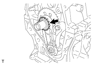 |
Remove the crankshaft timing sprocket.
| 21. REMOVE NO. 2 CHAIN SUB-ASSEMBLY |
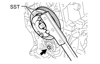 |
Temporarily install the crankshaft pulley with the pulley bolt.
Using SST, hold the crankshaft. Then remove the drive shaft gear nut.
Remove SST, the crankshaft pulley bolt and crankshaft pulley.
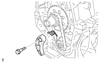 |
Remove the bolt, chain tensioner plate and spring.
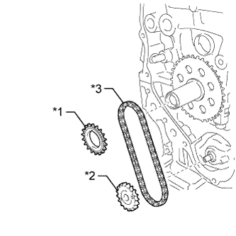 |
Remove the oil pump drive gear, oil pump drive shaft gear and No. 2 chain.
| *1 | Oil Pump Dive Gear |
| *2 | Oil Pump Drive Shaft Gear |
| *3 | No. 2 Chain Sub-Assembly |
| 22. REMOVE NO. 2 OIL PAN SUB-ASSEMBLY |
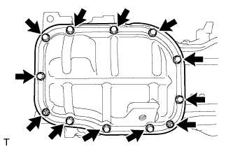 |
Remove the 10 bolts and 2 nuts.
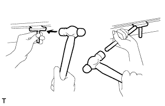 |
Insert the blade of an oil pan seal cutter between the crankcase and oil pan. Cut through the sealer and remove the oil pan.
| 23. REMOVE OIL PUMP ASSEMBLY |
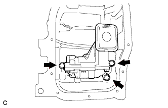 |
Remove the 3 bolts and oil pump.