DTC P0712 Transmission Fluid Temperature Sensor "A" Circuit Low Input |
DTC P0713 Transmission Fluid Temperature Sensor "A" Circuit High Input |
| DTC Code | DTC Detection Condition
| Trouble Area |
| P0712 |
|
|
| P0713 |
|
|
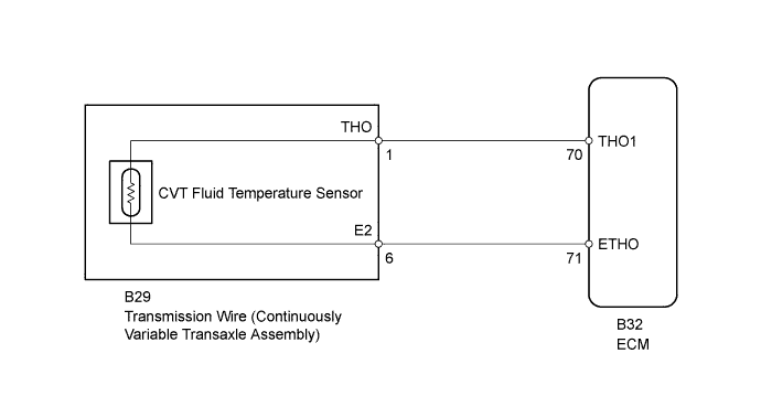
| 1.READ VALUE USING INTELLIGENT TESTER (A/T OIL TEMPERATURE 1) |
Warm up the engine.
Turn the ignition switch off.
Connect the intelligent tester to the DLC3.
Turn the ignition switch to ON.
Turn the intelligent tester on.
Enter the following menus: Powertrain / Engine and ECT / Data List.
In accordance with the display on the tester, read the Data List.
| Tester Display | Measurement Item/Range | Normal Condition | Diagnostic Note |
| A/T Oil Temperature 1 | CVT fluid temperature sensor value/ min.: -40°C (-40°F) max.: 215°C (419°F) |
| If the value is -40°C (-40°F) or 150°C (302°F) or more, the CVT fluid temperature sensor circuit is open or shorted. |
| Result | Proceed to |
| Data displayed is not as specified under Normal Condition | A |
| Data displayed is as specified under Normal Condition | B |
|
| ||||
| A | |
 |
| 2.INSPECT TRANSMISSION WIRE (CVT FLUID TEMPERATURE SENSOR) |
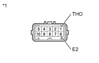 |
Disconnect the transmission wire connector.
Measure the resistance according to the value(s) in the table below.
| Tester Connection | Condition | Specified Condition |
| 1 (THO) - 6 (E2) | Always | 79 Ω to 156 kΩ |
| 1 (THO) - Body ground | Always | 10 kΩ or higher |
| 6 (E2) - Body ground | Always | 10 kΩ or higher |
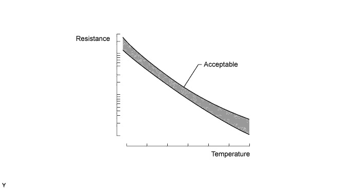
| CVT Fluid Temperature | Specified Condition |
| 10°C (50°F) | 5 to 8 kΩ |
| 25°C (77°F) | 2.5 to 4.5 kΩ |
| 110°C (230°F) | 0.22 to 0.28 kΩ |
| *1 | Component without harness connected (Transmission Wire) |
|
| ||||
| OK | |
|
| 3.CHECK HARNESS AND CONNECTOR (TRANSMISSION WIRE - ECM) |
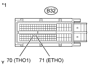 |
Disconnect the ECM connector.
Measure the resistance according to the value(s) in the table below.
| Tester Connection | Condition | Specified Condition |
| B32-70 (THO1) - B32-71 (ETHO) | Always | 79 Ω to 156 kΩ |
| B32-70 (THO1) - Body ground | Always | 10 kΩ or higher |
| B32-71 (ETHO) - Body ground | Always | 10 kΩ or higher |
| *1 | Front view of wire harness connector (to ECM) |
|
| ||||
| OK | |
|
| 4.REPLACE ECM |
Replace the ECM (Click here).
| NEXT | |
|
| 5.PERFORM INITIALIZATION |
| Replaced Part |
|
Using the intelligent tester, perform reset memory, deceleration sensor 0 point calibration and CVT oil pressure calibration (Click here).
Check that no DTC is stored.
| NEXT | ||
 | ||
| ||
| 6.REPLACE ECM |
Replace the ECM (Click here).
| NEXT | |
|
| 7.PERFORM INITIALIZATION |
| Replaced Part |
|
Using the intelligent tester, perform reset memory, deceleration sensor 0 point calibration and CVT oil pressure calibration (Click here).
Check that no DTC is stored.
| NEXT | ||
| ||
| ||
| 8.REPLACE CONTINUOUSLY VARIABLE TRANSAXLE ASSEMBLY |
Replace the continuously variable transaxle assembly (Click here).
| NEXT | |
|
| 9.PERFORM INITIALIZATION |
| Replaced Part |
|
Using the intelligent tester, perform reset memory, deceleration sensor 0 point calibration and CVT oil pressure calibration (Click here).
Check that no DTC is stored.
| NEXT | ||
| ||
| ||

