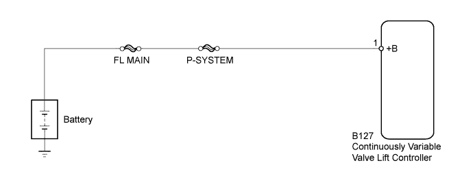
DTC P1047 Valvematic Driver Learned Value Error / Power Source Circuit Malfunction Bank 1 |
| DTC No. | DTC Detection Condition | Trouble Area |
| P1047 | The power supply to the continuously variable valve lift controller assembly is cut and the continuously variable valve lift controller internal valve lift control driver actuator position learned value cannot be learned or is abnormal (1 trip detection logic). |
|
| Actuator position learning is performed when these DTCs are stored. |
| P1046, P1049, P104A, P1055, P2646, P2647, P2648, P2649, P264A, U011B |
| 1.PERFORM SIMULATION TEST |
Perform a simulation test.
Connect the intelligent tester to the DLC3.
Stop the engine and wait 10 seconds.
Start the engine and idle it for 20 seconds.
Stop the engine and wait 10 seconds.
Turn the ignition switch to ON.
Turn the tester on.
Clear the DTCs (Click here).
Start the engine and idle it for 20 seconds.
Check if the MIL is illuminated during idling after clearing the DTCs in the above simulation test.
| Result | Proceed to |
| MIL illuminates | A |
| MIL does not illuminate | B |
|
| ||||
| A | |
 |
| 2.CHECK ANY OTHER DTCS OUTPUT |
Connect the intelligent tester to the DLC3.
Turn the ignition switch to ON.
Turn the intelligent tester on.
Enter the following menus: Powertrain / Engine and ECT / DTC.
Read the DTCs.
| Result | Proceed to |
| DTC P1047 is output | A |
| DTC P1047 and other DTCs are output | B |
|
| ||||
| A | |
|
| 3.CHECK CONTINUOUSLY VARIABLE VALVE LIFT CONTROLLER ASSEMBLY (POWER SOURCE) |
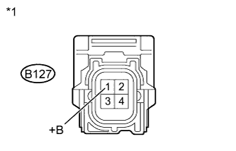 |
Disconnect the continuously variable valve lift controller assembly connector.
Measure the voltage according to the value(s) in the table below.
| Tester Connection | Switch Condition | Specified Condition |
| B127-1 (+B) - Body ground | Ignition switch ON | 11 to 14 V |
| *1 | Front view of wire harness connector (to Continuously Variable Valve Lift Controller) |
|
| ||||
| OK | ||
 | ||
| ||
