Home › Vehicle Interior › HEATING / AIR CONDITIONING › AIR CONDITIONING SYSTEM(for Manual Air Conditioning System)
RM30B0U _58 Vehicle Interior _009988 HEATING / AIR CONDITIONING _0054779 AIR CONDITIONING SYSTEM(for Manual Air Conditioning System) J

HEATING / AIR CONDITIONING  AIR CONDITIONING SYSTEM(for Manual Air Conditioning System)  Heater Control Switch Circuit  


DESCRIPTION

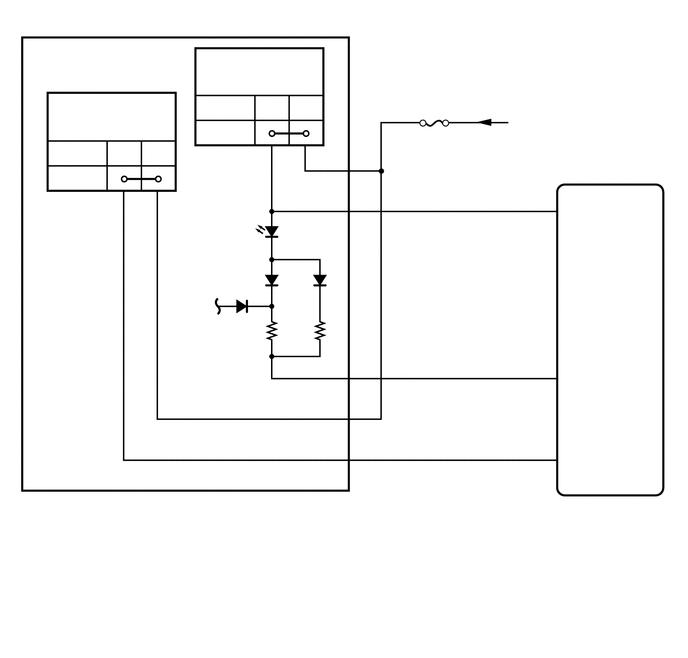
The No. 3 heater control sub-assembly is powered through the HTR-IG fuse. The No. 3 heater control sub-assembly transmits operational signals of each switch to the air conditioning amplifier assembly.

WIRING DIAGRAM
E269927
0.625,1.146 1.76,1.323 1.135,0.177 10 Max Hot Position 0.708,1.521 1.042,1.698 0.333,0.177 10 Off 0.708,1.76 1.073,1.938 0.365,0.177 10 On 2.375,0.667 3.323,0.885 0.948,0.219 10 A/C Switch 2.198,1.042 2.531,1.229 0.333,0.188 10 Free 2.198,1.302 2.552,1.49 0.354,0.188 10 Lock 3.469,1.792 3.635,1.958 0.167,0.167 10 B 3.677,1.583 3.844,1.75 0.167,0.167 10 2 3.333,2.25 3.646,2.417 0.313,0.167 10 A/C 3.677,2.01 3.844,2.177 0.167,0.167 10 3 3.677,3.719 3.844,3.885 0.167,0.167 10 4 3.677,4.594 3.844,4.76 0.167,0.167 10 8 3.26,3.969 3.625,4.135 0.365,0.167 10 AIND 3.479,4.813 3.656,4.969 0.177,0.156 10 E 3.479,4.385 3.656,4.542 0.177,0.156 10 B 3.688,4.177 3.854,4.344 0.167,0.167 10 7 5.854,4.719 6.302,4.896 0.448,0.177 10 HEAT 5.625,4.604 5.792,4.771 0.167,0.167 10 3 5.844,3.865 6.26,4.042 0.417,0.177 10 LED 5.583,3.76 5.75,3.927 0.167,0.167 10 12 5.854,2.125 6.146,2.281 0.292,0.156 10 A/C 5.656,2 5.771,2.177 0.115,0.177 10 2 4.313,1.354 4.802,1.531 0.49,0.177 10 HTR-IG 5.354,1.188 6.76,1.365 1.406,0.177 10 from IG1 NO.1 Relay 0.906,5.146 1.271,5.313 0.365,0.167 10 G23 0.906,5.344 3.365,5.552 2.458,0.208 10 No. 3 Heater Control Sub-assembly 5.75,5.198 6.198,5.375 0.448,0.177 10 G80 5.75,5.365 7.042,5.729 1.292,0.365 10 Air Conditioning Amplifier Assembly

CAUTION / NOTICE / HINT

NOTICE:

Inspect the fuses for circuits related to this system before performing the following procedure.


PROCEDURE
1.INSPECT NO. 3 HEATER CONTROL SUB-ASSEMBLY
a.
E269933
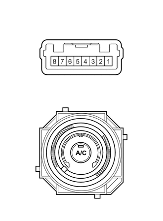
2.115,1.229 2.25,0.635 2.25,0.635 2.5,0.635 true 1.958,1.344 2.01,1.74 2.01,1.74 2.26,1.74 true 1.792,1.344 1.615,1.74 1.615,1.74 1.448,1.74 true 1.781,3.146 2.313,2.333 2.313,2.333 2.563,2.333 true 1.302,1.219 1.438,0.625 1.438,0.625 1.688,0.625 true 1.146,1.344 0.865,1.604 0.865,1.604 0.698,1.604 true 1.99,3.469 2.542,3.656 2.542,3.656 2.792,3.656 true 1.406,3.479 0.948,3.885 0.948,3.885 0.656,3.885 true 1.063,1.656 1.469,1.844 0.406,0.188 10 AIND 2.344,1.656 2.75,1.844 0.406,0.188 10 A/C 2.573,0.563 2.979,0.75 0.406,0.188 10 B 2.604,2.24 3.01,2.427 0.406,0.188 10 *1 1.74,0.563 2.146,0.75 0.406,0.188 10 B 0.531,1.51 0.938,1.698 0.406,0.188 10 E 2.833,3.552 3.24,3.74 0.406,0.188 10 *a 0.469,3.792 0.875,3.979 0.406,0.188 10 *b
*1 A/C Switch
*a Max hot position
*b Max cold position


Measure the resistance.


ii.

Measure the resistance according to the value(s) in the table below.

Standard Resistance:
Tester Connection Switch Condition Specified Condition
2 (B) - 3 (A/C) A/C switch on Below 1 Ω
2 (B) - 3 (A/C) A/C switch off 10 kΩ or higher
7 (B) - 8 (E) Max hot position Below 1 Ω
7 (B) - 8 (E) Other than max hot position 10 kΩ or higher


b.

Check that the indicator light comes on.

i.

Turn the A/C switch on.


ii.

Connect a positive (+) lead from the battery to terminal 2 (B) and negative (-) lead to terminal 4 (AIND), and check that the indicator light comes on.

OK:

The indicator light comes on.


Result:
Proceed to
OK
NG


OK

2.CHECK HARNESS AND CONNECTOR (NO. 3 HEATER CONTROL SUB-ASSEMBLY - BATTERY)

NG

2.CHECK HARNESS AND CONNECTOR (NO. 3 HEATER CONTROL SUB-ASSEMBLY - BATTERY)
a.
E269926
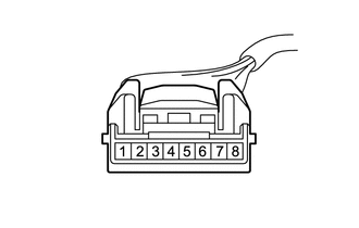
1.5,0.333 1.906,0.604 0.406,0.271 0.875,1.854 1.115,1.854 1.115,1.854 1.344,1.469 true 2.396,1.885 2.25,1.885 2.25,1.885 2.104,1.479 true 1.573,0.396 2.031,0.594 0.458,0.198 10 G23 0.052,0.052 0.51,0.25 0.458,0.198 10 *a 0.708,1.771 0.896,1.958 0.188,0.188 10 B 2.438,1.813 2.792,2 0.354,0.188 10 B
*a Front view of wire harness connector
(to No. 3 Heater Control Sub-assembly)


Disconnect the No. 3 heater control sub-assembly connector.


b.

Measure the voltage according to the value(s) in the table below.

Standard Voltage:
Tester Connection Switch Condition Specified Condition
G23-2 (B) - Body ground Ignition switch ON 11 to 14 V
G23-2 (B) - Body ground Ignition switch off Below 1 V
G23-7 (B) - Body ground Ignition switch ON 11 to 14 V
G23-7 (B) - Body ground Ignition switch off Below 1 V


Result:
Proceed to
OK
NG


OK

3.CHECK HARNESS AND CONNECTOR (NO. 3 HEATER CONTROL SUB-ASSEMBLY - AIR CONDITIONING AMPLIFIER ASSEMBLY)

NG

REPAIR OR REPLACE HARNESS OR CONNECTOR

3.CHECK HARNESS AND CONNECTOR (NO. 3 HEATER CONTROL SUB-ASSEMBLY - AIR CONDITIONING AMPLIFIER ASSEMBLY)
a.

Disconnect the G23 No. 3 heater control sub-assembly connector.


b.

Disconnect the G80 air conditioning amplifier assembly connector.


c.

Measure the resistance according to the value(s) in the table below.

Standard Resistance:
Tester Connection Condition Specified Condition
G23-3 (A/C) - G80-2 (A/C) Always Below 1 Ω
G23-4 (AIND) - G80-12 (LED) Always Below 1 Ω
G23-8 (E) - G80-3 (HEAT) Always Below 1 Ω
G23-3 (A/C) - Body ground Always 10 kΩ or higher
G23-4 (AIND) - Body ground Always 10 kΩ or higher
G23-8 (E) - Body ground Always 10 kΩ or higher


Result:
Proceed to
OK
NG


OK

NG

REPAIR OR REPLACE HARNESS OR CONNECTOR