RM30B0U
_59
Vehicle Exterior
_010071
LIGHTING (EXT)
_0055114
STOP LIGHT SWITCH
A
LIGHTING (EXT) STOP LIGHT SWITCH INSTALLATION
PROCEDURE

 1.INSTALL STOP LIGHT SWITCH MOUNTING ADJUSTER
a.
Attach the 2 claws to install a new stop light switch mounting adjuster.
2.INSTALL STOP LIGHT SWITCH ASSEMBLY
a.
2.042,1.823 2.01,1.542
false
1.188,1.865 1.104,1.417
false
0.521,1.49 0.781,1.427
false
0.344,1.427 0.656,1.583
0.313,0.156
10
*1
1.146,1.865 1.458,2.021
0.313,0.156
10
*2
1.99,1.833 2.302,1.99
0.313,0.156
10
*3
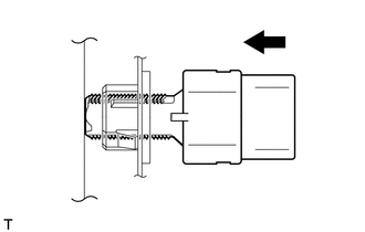
| *1 | Brake Pedal |
| *2 | Stop Light Switch Mounting Adjuster |
| *3 | Stop Light Switch Assembly |
Install the stop light switch assembly to the adjuster until the switch body slightly touches the brake pedal.
- NOTICE:
-
Do not depress the brake pedal.
b.
2.021,1.875 1.979,1.552
false
0.406,1.104 0.708,1.104
false
0.26,1.042 0.573,1.198
0.313,0.156
10
*1
0.979,1.76 1.292,1.917
0.313,0.156
10
*2
1.958,1.885 2.271,2.042
0.313,0.156
10
*3
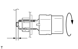
| *1 | Shaft |
| *2 | 0.5 to 2.6 mm (0.0197 to 0.102 in.) |
| *3 | Stop Light Switch Assembly |
Rotate the stop light switch assembly clockwise so that the clearance is between 0.5 and 2.6 mm (0.0197 to 0.102 in.) as shown in the illustration.
- NOTICE:
-
Do not depress the brake pedal.
c.
Check the stop light switch assembly clearance.
- Stop light switch clearance:
0.5 to 2.6 mm (0.0197 to 0.102 in.)
d.
Connect the connector to the stop light switch assembly.
3.INSTALL NO. 1 INSTRUMENT PANEL UNDER COVER SUB-ASSEMBLY