Home › Vehicle Exterior › LIGHTING (EXT) › AUTOMATIC HEADLIGHT BEAM LEVEL CONTROL SYSTEM
RM3090E _59 Vehicle Exterior _008430 LIGHTING (EXT) _0047056 AUTOMATIC HEADLIGHT BEAM LEVEL CONTROL SYSTEM J

LIGHTING (EXT)  AUTOMATIC HEADLIGHT BEAM LEVEL CONTROL SYSTEM  Warning Light Circuit  


DESCRIPTION

The headlight beam level control system warning light in the combination meter comes on for approximately 3 seconds when the ignition switch is turned to ON. The warning light also comes on when the headlight leveling ECU detects a malfunction.

WIRING DIAGRAM
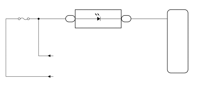
E270530
0.594,0.708 1.365,0.906 0.771,0.198 10 METER 2.302,0.552 2.635,0.76 0.333,0.208 10 G16 4.219,0.563 4.573,0.74 0.354,0.177 10 G17 3.698,0.448 4.25,0.646 0.552,0.198 10 LVWG 2.656,0.469 2.969,0.667 0.313,0.198 10 IG+ 2.333,0.365 2.604,0.563 0.271,0.198 10 39 4.313,0.354 4.583,0.552 0.271,0.198 10 4 5.594,0.427 5.865,0.625 0.271,0.198 10 6 2.521,1.01 4.552,1.24 2.031,0.229 10 Combination Meter Assembly 1.969,1.813 4.281,2.021 2.313,0.208 10 from Engine Stop and Start ECU*1 1.938,2.51 3.188,2.729 1.25,0.219 10 from IG2 Relay*2 4.979,2.573 7.115,2.823 2.135,0.25 10 Headlight Leveling ECU Assembly 4.969,2.396 5.417,2.594 0.448,0.198 10 A67 5.844,0.563 6.292,0.76 0.448,0.198 10 WNG 0.167,3.083 2.083,3.302 1.917,0.219 10 *1: w/ Stop and Start System 0.177,3.375 2.333,3.594 2.156,0.219 10 *2: w/o Stop and Start System

CAUTION / NOTICE / HINT

HINT:

Inspect the fuses for circuits related to this system before performing the following inspection procedure.


PROCEDURE

1.INSPECT COMBINATION METER ASSEMBLY
a.

Remove the combination meter assembly.

Click hereVehicle Interior>METER / GAUGE / DISPLAY>COMBINATION METER>REMOVAL
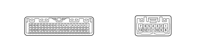
E270531
1.74,0.188 2.156,0.438 0.417,0.25 5.01,0.219 5.427,0.469 0.417,0.25 5.24,1.313 5.24,0.948 false 1.146,1.448 1.146,1.083 false 1.896,0.229 2.052,0.427 0.156,0.198 10 A 5.177,0.25 5.333,0.448 0.156,0.198 10 B 1.042,1.469 1.438,1.646 0.396,0.177 10 IG+ 5.125,1.354 5.708,1.531 0.583,0.177 10 LVWG


b.

Connect the positive (+) lead from the battery to terminal A-39 (IG+) and the negative (-) lead to terminal B-4 (LVWG).


c.

Check that the warning light comes on.


Result:
Proceed to
Warning light comes on
Warning light does not comes on


Warning light comes on

2.CHECK HARNESS AND CONNECTOR (COMBINATION METER ASSEMBLY - BATTERY)

Warning light does not comes on

REPLACE COMBINATION METER ASSEMBLY

2.CHECK HARNESS AND CONNECTOR (COMBINATION METER ASSEMBLY - BATTERY)
a.
B143726
1.521,0.708 1.917,0.917 0.396,0.208 2.5,2 2.698,1.719 false 0.115,0.104 0.427,0.302 0.313,0.198 10 *a 1.583,0.729 2.063,0.917 0.479,0.188 10 G16 2.25,1.969 2.729,2.156 0.479,0.188 10 IG+
*a Front view of wire harness connector
(to Combination Meter Assembly)


Disconnect the G16 combination meter connector.


b.

Measure the voltage according to the value(s) in the table below.

Standard Voltage:
Tester Connection Switch Condition Specified Condition

*1: w/ Stop and Start System

*2: w/o Stop and Start System

G16-39 (IG+) - Body ground Ignition switch ON 10.5 to 14 V*1
Ignition switch ON 11 to 14 V*2
Ignition switch off Below 1 V


Result:
Proceed to
OK
NG


OK

3.CHECK HARNESS AND CONNECTOR (COMBINATION METER ASSEMBLY - HEADLIGHT LEVELING ECU ASSEMBLY)

NG

REPAIR OR REPLACE HARNESS OR CONNECTOR

3.CHECK HARNESS AND CONNECTOR (COMBINATION METER ASSEMBLY - HEADLIGHT LEVELING ECU ASSEMBLY)
a.

Disconnect the G17 combination meter connector.


b.

Disconnect the A67 headlight leveling ECU connector.


c.

Measure the resistance according to the value(s) in the table below.

Standard Resistance:
Tester Connection Condition Specified Condition
A67-6 (WNG) - G17-4 (LVWG) Always Below 1 Ω
A67-6 (WNG) - Body ground Always 10 kΩ or higher


Result:
Proceed to
OK
NG


OK

PROCEED TO NEXT SUSPECTED AREA SHOWN IN PROBLEM SYMPTOMS TABLE

NG

REPAIR OR REPLACE HARNESS OR CONNECTOR