BRAKE CONTROL / DYNAMIC CONTROL SYSTEMS VEHICLE STABILITY CONTROL SYSTEM C1379 Downhill Assist Control Switch Malfunction (Test Mode DTC)
DESCRIPTION
DTC C1379 is cleared when the downhill assist control switch sends a downhill assist control operation signal or when test mode ends.
| DTC No. | Detection Item | DTC Detection Condition | Trouble Area |
|---|---|---|---|
| C1379 | Downhill Assist Control Switch Malfunction (Test Mode DTC) | Stored only during test mode. | ·
Downhill assist control switch ·
Harness or connector ·
Skid control ECU (Brake actuator assembly) |
WIRING DIAGRAM
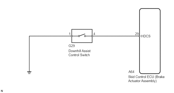
CAUTION / NOTICE / HINT
- NOTICE:
-
When replacing the skid control ECU (brake actuator assembly), perform zero point calibration.
-
Click hereBrake>BRAKE CONTROL / DYNAMIC CONTROL SYSTEMS>VEHICLE STABILITY CONTROL SYSTEM>CALIBRATION
PROCEDURE
Turn the ignition switch off.
Connect the GTS to the DLC3.
Turn the ignition switch to ON.
Turn the GTS on.
Enter the following menus: Chassis / ABS/VSC/TRC / Data List.
Check the Data List for proper functioning of the downhill assist control switch.
- Chassis > ABS/VSC/TRC > Data List
-
Tester Display Measurement Item Range Normal Condition Diagnostic Note Downhill Assist Control SW Downhill assist control switch ON or OFF OFF: Downhill assist control switch off
ON: Downhill assist control switch on-
- Chassis > ABS/VSC/TRC > Data List
-
Tester Display Downhill Assist Control SW - 50003 105 260
- OK:
The GTS displays ON or OFF according to downhill assist control switch operation.
- Result:
Result OK NG
OK
NG
Perform the downhill assist control switch check in the Test Mode Procedure.
Click hereBrake>BRAKE CONTROL / DYNAMIC CONTROL SYSTEMS>VEHICLE STABILITY CONTROL SYSTEM>TEST MODE PROCEDURE
- Chassis > ABS/VSC/TRC > Utility
-
Tester Display Signal Check - 50005 105 3
- OK:
Test mode DTC C1379 is cleared.
- Result:
Result OK NG
OK
Click hereGeneral>INTRODUCTION>HOW TO TROUBLESHOOT ECU CONTROLLED SYSTEMS>HOW TO PROCEED WITH TROUBLESHOOTING
NG
Remove the downhill assist control switch.
Click hereBrake>BRAKE CONTROL / DYNAMIC CONTROL SYSTEMS>DOWNHILL ASSIST CONTROL SWITCH>REMOVAL
Inspect the downhill assist control switch.
Click hereBrake>BRAKE CONTROL / DYNAMIC CONTROL SYSTEMS>DOWNHILL ASSIST CONTROL SWITCH>INSPECTION
- Result:
Result OK NG
OK
NG
Disconnect the A64 skid control ECU (brake actuator assembly) connector.
Measure the resistance according to the value(s) in the table below.
- Standard Resistance:
Tester Connection Condition Specified Condition A64-29 (HDCS) - G29-4 Always Below 1 Ω A64-29 (HDCS) or G29-4 - Body ground Always 10 kΩ or higher G29-1 - Body ground Always Below 1 Ω
- Result:
Result OK NG
OK
NG