U660F AUTOMATIC TRANSMISSION / TRANSAXLE AIR COOLED OIL COOLER INSTALLATION
PROCEDURE

 32910
1.INSTALL OIL COOLER ASSEMBLY
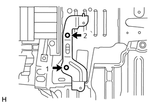
Install the No. 1 oil cooler bracket with the 2 bolts. Tighten the bolts in the order shown in the illustration.
- Torque:
- 5.5 N*m (56 kgf*cm, 49 in.*lbf)
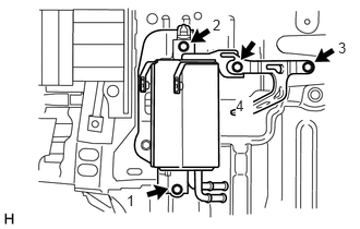
Install the oil cooler assembly and No. 2 oil cooler bracket with the 4 bolts. Tighten the bolts in the order shown in the illustration.
- Torque:
- 5.5 N*m (56 kgf*cm, 49 in.*lbf)
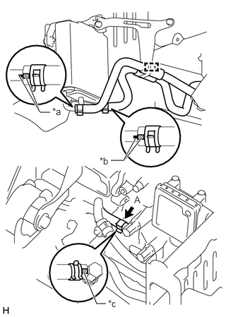
| *a | Yellow Paint Mark |
| *b | White Paint Mark |
| *c | Pink Paint Mark |
Connect the hose clamp and install the oil cooler hose assembly, and slide the clips to secure it.
- NOTICE:
- ·
Make sure the paint marks are aligned as shown in the illustration.
·Make sure that the claws marked A in the illustration are facing toward the front end of the vehicle.
·Position the claws of the clips so that they do not interfere with other parts unless otherwise specified.
2.INSTALL TRANSMISSION OIL COOLER AIR DUCT
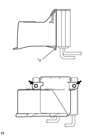
| *a | Rib |
Attach the rib of the transmission oil cooler air duct, and then temporarily install the oil cooler assembly with the 2 bolts.
Tighten the 2 bolts.
- Torque:
- 5.5 N*m (56 kgf*cm, 49 in.*lbf)
32906
3.INSTALL OIL COOLER TUBE SUB-ASSEMBLY
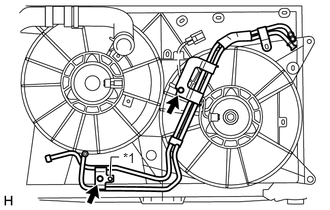
| *1 | Pin |
Install the oil cooler tube sub-assembly with the 2 bolts. Tighten the bolts in the order shown in the illustration.
- Torque:
- 5.5 N*m (56 kgf*cm, 49 in.*lbf)
- NOTICE:
-
Insert the pin of the radiator fan shroud into the hole of the oil cooler tube sub-assembly.
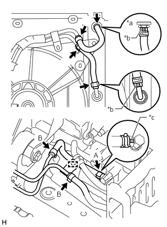
| *a | Upper View |
| *b | Yellow Paint Mark |
| *c | Green Paint Mark |
Install the No. 1 oil cooler inlet hose, No. 2 oil cooler inlet hose and No. 2 oil cooler outlet hose, and slide the clips to secure it.
- NOTICE:
- ·
Make sure that the paint marks are in the position shown in the illustration.
·Make sure that the claws marked A in the illustration are facing toward the front end of the vehicle, and that the claws marked B in the illustration are facing toward the underside of the vehicle.
·Position the claws of the clips so that they do not interfere with other parts unless otherwise specified.
4.ADD AUTOMATIC TRANSAXLE FLUID
5.ADJUST AUTOMATIC TRANSAXLE FLUID
52119A
6.INSTALL FRONT BUMPER COVER
51444C
7.INSTALL REAR ENGINE UNDER COVER LH
51441
8.INSTALL NO. 1 ENGINE UNDER COVER