Home › Vehicle Exterior › WIPER / WASHER › WIPER AND WASHER SYSTEM(w/ Rain Sensor)
RM3090E _59 Vehicle Exterior _008795 WIPER / WASHER _0050248 WIPER AND WASHER SYSTEM(w/ Rain Sensor) J

WIPER / WASHER  WIPER AND WASHER SYSTEM(w/ Rain Sensor)  Wiper and Washer Switch Circuit  


DESCRIPTION

This circuit detects the state of the windshield wiper switch assembly and sends it to the windshield wiper relay assembly.

WIRING DIAGRAM
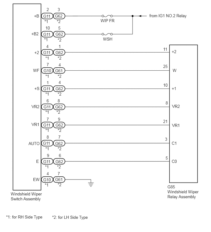
E270594E02
0.365,6.49 1.5,6.896 1.135,0.406 10 false Windshield Wiper Switch Assembly 5.688,6.417 6.781,6.833 1.094,0.417 10 false Windshield Wiper Relay Assembly 1.469,0.469 1.927,0.667 0.458,0.198 10 false G11 1.865,0.458 2.323,0.656 0.458,0.198 10 false G62 1.469,1.083 1.927,1.281 0.458,0.198 10 false G11 1.469,1.698 1.927,1.896 0.458,0.198 10 false G11 1.479,2.313 1.938,2.51 0.458,0.198 10 false G10 1.469,2.927 1.927,3.125 0.458,0.198 10 false G11 1.479,3.542 1.938,3.74 0.458,0.198 10 false G11 1.469,4.156 1.927,4.354 0.458,0.198 10 false G11 1.458,4.771 1.917,4.969 0.458,0.198 10 false G11 1.469,5.396 1.927,5.594 0.458,0.198 10 false G11 1.469,6.01 1.927,6.208 0.458,0.198 10 false G10 1.885,1.073 2.344,1.271 0.458,0.198 10 false G62 1.885,1.698 2.344,1.896 0.458,0.198 10 false G62 1.875,2.313 2.333,2.51 0.458,0.198 10 false G61 1.885,2.927 2.344,3.125 0.458,0.198 10 false G62 1.875,3.542 2.333,3.74 0.458,0.198 10 false G62 1.885,4.156 2.344,4.354 0.458,0.198 10 false G62 1.875,4.781 2.333,4.979 0.458,0.198 10 false G62 1.885,5.396 2.344,5.594 0.458,0.198 10 false G62 1.875,6 2.333,6.198 0.458,0.198 10 false G61 1.583,0.24 2.042,0.438 0.458,0.198 10 false 2 1.958,0.24 2.417,0.438 0.458,0.198 10 false 3 1.156,0.458 1.615,0.656 0.458,0.198 10 false +B 1.51,0.646 1.969,0.844 0.458,0.198 10 false *1 1.927,0.646 2.385,0.844 0.458,0.198 10 false *2 1.542,0.865 2,1.063 0.458,0.198 10 false 10 1.979,0.865 2.438,1.063 0.458,0.198 10 false 5 3.417,0.615 4.333,0.813 0.917,0.198 10 false WIP FR 3.5,1.24 3.958,1.438 0.458,0.198 10 false WSH 1.063,1.063 1.521,1.26 0.458,0.198 10 false +B2 1.99,1.49 2.448,1.688 0.458,0.198 10 false 1 1.5,1.26 1.958,1.458 0.458,0.198 10 false *1 1.958,1.271 2.417,1.469 0.458,0.198 10 false *2 1.542,1.885 2,2.083 0.458,0.198 10 false *1 1.958,1.885 2.417,2.083 0.458,0.198 10 false *2 1.583,2.104 2.042,2.302 0.458,0.198 10 false 7 1.99,2.115 2.448,2.313 0.458,0.198 10 false 4 1.542,2.5 2,2.698 0.458,0.198 10 false *1 1.958,2.5 2.417,2.698 0.458,0.198 10 false *2 1.167,1.698 1.625,1.896 0.458,0.198 10 false +2 1.167,2.917 1.625,3.115 0.458,0.198 10 false +S 1.073,3.531 1.531,3.729 0.458,0.198 10 false VR2 1.073,4.135 1.531,4.333 0.458,0.198 10 false VR1 0.969,4.781 1.583,4.979 0.615,0.198 10 false AUTO 1.229,5.385 1.688,5.583 0.458,0.198 10 false E 1.125,6 1.74,6.198 0.615,0.198 10 false EW 5.688,6.25 6.146,6.448 0.458,0.198 10 false G85 5.833,1.667 6.292,1.865 0.458,0.198 10 false +2 1.125,2.302 1.583,2.5 0.458,0.198 10 false WF 5.865,2.302 6.323,2.5 0.458,0.198 10 false W 5.833,2.917 6.292,3.115 0.458,0.198 10 false +1 5.844,3.521 6.302,3.719 0.458,0.198 10 false VR2 5.844,4.167 6.302,4.365 0.458,0.198 10 false VR1 5.833,4.771 6.448,4.969 0.615,0.198 10 false C1 5.833,5.385 6.292,5.583 0.458,0.198 10 false C0 5.073,0.448 7.156,0.688 2.083,0.24 10 false from IG1 NO.2 Relay 5.542,1.583 6,1.781 0.458,0.198 10 false 11 5.542,2.167 6,2.365 0.458,0.198 10 false 25 5.542,2.802 6,3 0.458,0.198 10 false 10 5.625,3.406 6.083,3.604 0.458,0.198 10 false 8 5.542,4.031 6,4.229 0.458,0.198 10 false 21 5.604,4.635 6.063,4.833 0.458,0.198 10 false 3 5.625,5.271 6.083,5.469 0.458,0.198 10 false 5 1.573,1.49 2.031,1.688 0.458,0.198 10 false 4 1.542,3.104 2,3.302 0.458,0.198 10 false *1 1.958,3.104 2.417,3.302 0.458,0.198 10 false *2 0.208,7.271 3.271,7.469 3.063,0.198 10 false *1: for RH Side Type 1.771,7.281 4.833,7.479 3.063,0.198 10 false *2: for LH Side Type 1.542,3.719 2,3.917 0.458,0.198 10 false *1 1.917,3.719 2.375,3.917 0.458,0.198 10 false *2 1.542,4.333 2,4.531 0.458,0.198 10 false *1 1.958,4.333 2.417,4.531 0.458,0.198 10 false *2 1.542,4.958 2,5.156 0.458,0.198 10 false *1 1.958,4.958 2.417,5.156 0.458,0.198 10 false *2 1.531,5.573 1.99,5.771 0.458,0.198 10 false *1 1.938,5.573 2.396,5.771 0.458,0.198 10 false *2 1.521,6.188 1.979,6.385 0.458,0.198 10 false *1 1.958,6.177 2.417,6.375 0.458,0.198 10 false *2 1.583,2.719 2.042,2.917 0.458,0.198 10 false 1 1.99,2.708 2.448,2.906 0.458,0.198 10 false 4 1.583,3.333 2.042,3.531 0.458,0.198 10 false 6 1.958,3.333 2.417,3.531 0.458,0.198 10 false 8 1.583,3.958 2.042,4.156 0.458,0.198 10 false 7 1.969,3.958 2.427,4.156 0.458,0.198 10 false 9 1.583,4.563 2.042,4.76 0.458,0.198 10 false 8 1.979,4.563 2.438,4.76 0.458,0.198 10 false 7 1.594,5.188 2.052,5.385 0.458,0.198 10 false 9 2,5.188 2.458,5.385 0.458,0.198 10 false 6 1.583,5.802 2.042,6 0.458,0.198 10 false 4 1.958,5.802 2.417,6 0.458,0.198 10 false 7

CAUTION / NOTICE / HINT

NOTICE:

Inspect the fuses for circuits related to this system before performing the following inspection procedure.


PROCEDURE

1.INSPECT WINDSHIELD WIPER SWITCH ASSEMBLY
a.

Remove the windshield wiper switch assembly.

Click hereVehicle Exterior>WIPER / WASHER>WIPER SWITCH>REMOVAL


b.

Inspect the windshield wiper switch assembly.

Click hereVehicle Exterior>WIPER / WASHER>WIPER SWITCH>INSPECTION


Result:
Proceed to
OK
NG


OK

2.CHECK HARNESS AND CONNECTOR (WINDSHIELD WIPER SWITCH ASSEMBLY - BATTERY AND BODY GROUND)

NG

REPLACE WINDSHIELD WIPER SWITCH ASSEMBLY

2.CHECK HARNESS AND CONNECTOR (WINDSHIELD WIPER SWITCH ASSEMBLY - BATTERY AND BODY GROUND)
a.
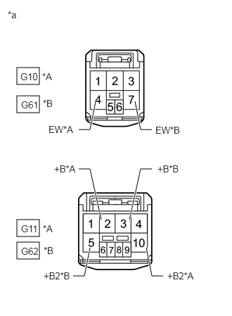
E270601C01
0.25,1 0.583,1.25 0.333,0.25 0.25,3.25 0.583,3.5 0.333,0.25 0.25,1.417 0.583,1.667 0.333,0.25 0.25,3.583 0.583,3.833 0.333,0.25 2.25,1.917 2.083,1.917 2.083,1.917 2,1.5 true 1.333,3.667 1.25,4.083 1.25,4.083 1.083,4.083 true 1.5,3.25 1.333,2.5 1.333,2.5 1.167,2.5 true 1.917,3.25 2.083,2.5 2.083,2.5 2.25,2.5 true 1.167,1.917 1.333,1.917 1.333,1.917 1.417,1.5 true 2.167,3.667 2.25,4.083 2.25,4.083 2.417,4.083 true 0.115,0.135 0.427,0.333 0.313,0.198 10 *a 0.302,1.052 1.073,1.25 0.771,0.198 10 G10 0.625,1.052 0.938,1.25 0.313,0.198 10 *A 0.313,3.302 1.083,3.5 0.771,0.198 10 G11 0.635,3.302 0.948,3.5 0.313,0.198 10 *A 0.313,1.469 1.083,1.667 0.771,0.198 10 G61 0.635,1.448 0.948,1.646 0.313,0.198 10 *B 0.313,3.635 1.083,3.833 0.771,0.198 10 G62 0.646,3.625 0.958,3.823 0.313,0.198 10 *B 0.719,1.833 1.333,2.031 0.615,0.198 10 EW*A 2.302,1.844 2.917,2.042 0.615,0.198 10 EW*B 0.802,2.417 1.417,2.615 0.615,0.198 10 +B*A 2.333,2.417 2.948,2.615 0.615,0.198 10 +B*B 2.479,4 3.25,4.198 0.771,0.198 10 +B2*A 0.646,4 1.417,4.198 0.771,0.198 10 +B2*B
*A for RH Side Type
*B for LH Side Type
*a Front view of wire harness connector
(to Windshield Wiper Switch Assembly)


Disconnect the windshield wiper assembly connectors.


b.

Measure the resistance according to the value(s) in the table below.

Standard Resistance:
for RH Side Type
Tester Connection Condition Specified Condition
G10-4 (EW) -Body ground Always Below 1 Ω

for LH Side Type
Tester Connection Condition Specified Condition
G61-7 (EW) -Body ground Always Below 1 Ω


c.

Measure the voltage according to the value(s) in the table below.

Standard Voltage:
for RH Side Type
Tester Connection Switch Condition Specified Condition
G11-2 (+B) -Body ground Ignition switch ON 11 to 14 V
Ignition switch off Below 1 V
G11-10 (+B2) -Body ground Ignition switch ON 11 to 14 V
Ignition switch off Below 1 V

for LH Side Type
Tester Connection Switch Condition Specified Condition
G62-3 (+B) -Body ground Ignition switch ON 11 to 14 V
Ignition switch off Below 1 V
G62-5 (+B2) -Body ground Ignition switch ON 11 to 14 V
Ignition switch off Below 1 V


Result:
Proceed to
OK
NG


OK

3.CHECK HARNESS AND CONNECTOR (WINDSHIELD WIPER SWITCH ASSEMBLY - WINDSHIELD WIPER RELAY ASSEMBLY)

NG

REPAIR OR REPLACE HARNESS OR CONNECTOR

3.CHECK HARNESS AND CONNECTOR (WINDSHIELD WIPER SWITCH ASSEMBLY - WINDSHIELD WIPER RELAY ASSEMBLY)
a.

Disconnect the G10*1 and G11*1 or G61*2 and G62*2 windshield wiper switch assembly connectors.

*1: for RH Side Type

*2: for LH Side Type


b.

Disconnect the G85 windshield wiper relay assembly connector.


c.

Measure the resistance according to the value(s) in the table below.

Standard Resistance:
for RH Side Type
Tester Connection Condition Specified Condition
G11-4 (+2) - G85-11 (+2) Always Below 1 Ω
G10-7 (WF) - G85-25 (W) Always Below 1 Ω
G11-1 (+S) - G85-10 (+1) Always Below 1 Ω
G11-6 (VR2) - G85-8 (VR2) Always Below 1 Ω
G11-7 (VR1) - G85-21 (VR1) Always Below 1 Ω
G11-8 (AUTO) - G85-3 (C1) Always Below 1 Ω
G11-9 (E) - G85-5 (C0) Always Below 1 Ω
G11-4 (+2) - Body ground Always 10 kΩ or higher
G10-7 (WF) - Body ground Always 10 kΩ or higher
G11-1 (+S) - Body ground Always 10 kΩ or higher
G11-6 (VR2) - Body ground Always 10 kΩ or higher
G11-7 (VR1) - Body ground Always 10 kΩ or higher
G11-8 (AUTO) - Body ground Always 10 kΩ or higher
G11-9 (E) - Body ground Always 10 kΩ or higher

for LH Side Type
Tester Connection Condition Specified Condition
G62-1 (+2) - G85-11 (+2) Always Below 1 Ω
G61-4 (WF) - G85-25 (W) Always Below 1 Ω
G62-4 (+S) - G85-10 (+1) Always Below 1 Ω
G62-8 (VR2) - G85-8 (VR2) Always Below 1 Ω
G62-9 (VR1) - G85-21 (VR1) Always Below 1 Ω
G62-7 (AUTO) - G85-3 (C1) Always Below 1 Ω
G62-6 (E) - G85-5 (C0) Always Below 1 Ω
G62-1 (+2) - Body ground Always 10 kΩ or higher
G61-4 (WF) - Body ground Always 10 kΩ or higher
G62-4 (+S) - Body ground Always 10 kΩ or higher
G62-8 (VR2) - Body ground Always 10 kΩ or higher
G62-9 (VR1) - Body ground Always 10 kΩ or higher
G62-7 (AUTO) - Body ground Always 10 kΩ or higher
G62-6 (E) - Body ground Always 10 kΩ or higher


Result:
Proceed to
OK
NG


OK

PROCEED TO NEXT SUSPECTED AREA SHOWN IN PROBLEM SYMPTOMS TABLE

NG

REPAIR OR REPLACE HARNESS OR CONNECTOR