EB63 MANUAL TRANSMISSION / TRANSAXLE OUTPUT SHAFT REASSEMBLY
PROCEDURE

 33321N
1.INSTALL FRONT OUTPUT SHAFT BEARING
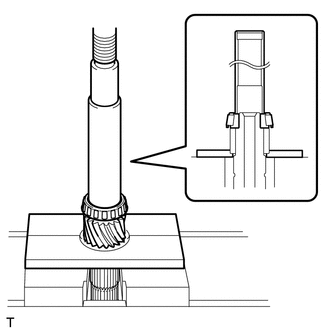
Using SST and a press, press a new front output shaft bearing onto the output shaft.
- SST
- 09527-21011
09608-06041
33345
2.INSTALL 1ST GEAR BUSH
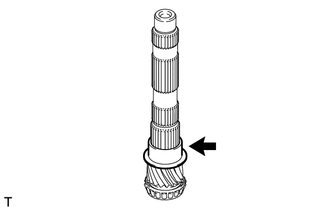
Coat the 1st gear bush with gear oil and install it to the output shaft.
33335C
3.INSTALL 1ST GEAR NEEDLE ROLLER BEARING
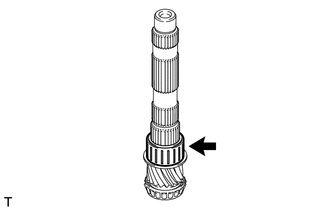
Coat the 1st gear needle roller bearing with gear oil and install it to the output shaft.
33335
4.INSTALL 1ST GEAR
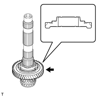
Coat the 1st gear with gear oil and install it to the output shaft.
- NOTICE:
-
Install the 1st gear as shown in the illustration.
33037B
5.INSTALL NO. 1 SYNCHRONIZER RING SET (for 1st Gear)
Coat the 1st gear cone and No. 1 synchronizer ring set (inner ring, middle ring and outer ring) with gear oil.
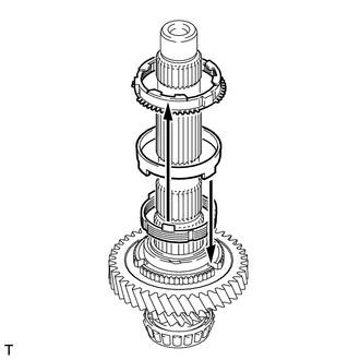
| *1 | Outer Ring |
| *2 | Middle Ring |
| *3 | Inner Ring |
Install the inner ring to the 1st gear.
Install the middle ring to the 1st gear.
- NOTICE:
-
Attach the claws of the middle ring to the grooves of the 1st gear.
Install the outer ring to the 1st gear.
- NOTICE:
-
Align the claws of the inner ring with the grooves of the outer ring before installing the outer ring.
33361
6.INSTALL NO. 1 TRANSMISSION CLUTCH HUB
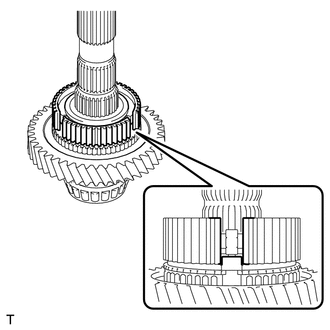
Install the No. 1 transmission clutch hub to the output shaft.
- NOTICE:
-
Align the cutout of the No. 1 transmission clutch hub with the protrusion of the outer ring as shown in the illustration.
33365
7.INSTALL NO. 1 SYNCHROMESH SHIFTING KEY
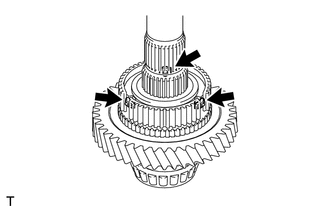
Install the 3 No. 1 synchromesh shifting keys to the No. 1 transmission clutch hub.
33331
8.INSTALL REVERSE GEAR
Coat the reverse gear and No. 1 transmission clutch hub with gear oil.
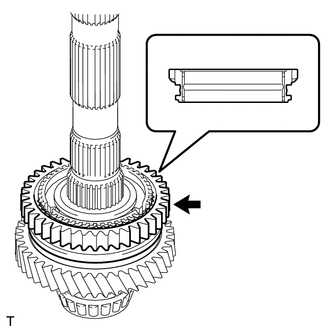
Install the reverse gear to the No. 1 transmission clutch hub.
- NOTICE:
-
Install the reverse gear as shown in the illustration.
33037B
9.INSTALL NO. 1 SYNCHRONIZER RING SET (for 2nd Gear)
Coat the 2nd gear cone and No. 1 synchronizer ring set (inner ring, middle ring and outer ring) with gear oil.
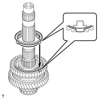
Install the outer ring to the No. 1 transmission clutch hub.
- NOTICE:
-
Align the protrusion of the outer ring with the cutout of the No. 1 transmission clutch hub before installing the outer ring.
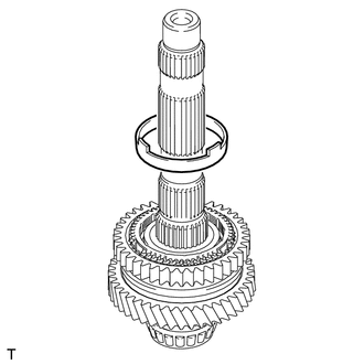
Install the middle ring to the outer ring.
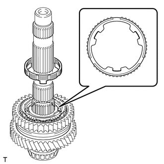
| *1 | Inner Ring |
| *2 | Outer Ring |
| *a | Cutout |
Install the inner ring to the middle ring.
- NOTICE:
-
Align the cutouts of the outer ring with the protrusions of the inner ring before installing the inner ring.
33356A
10.INSTALL INNER 2ND GEAR BEARING RACE
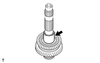
Coat the inner 2nd gear bearing race with gear oil and install it to the output shaft.
33332B
11.INSTALL 2ND GEAR NEEDLE ROLLER BEARING
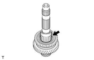
Coat the 2nd gear needle roller bearing with gear oil and install it to the output shaft.
33332
12.INSTALL 2ND GEAR
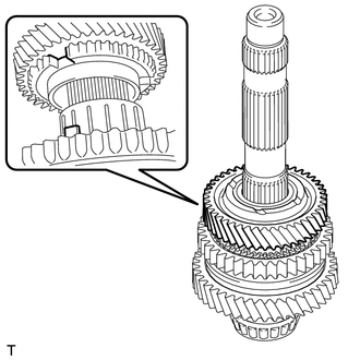
| *a | Groove |
| *b | Claw |
Coat the 2nd gear with gear oil and install it to the output shaft.
- NOTICE:
-
Align the claw of the middle ring with the groove of the 2nd gear before installing the 2nd gear.
33423A
13.INSTALL 3RD DRIVEN GEAR
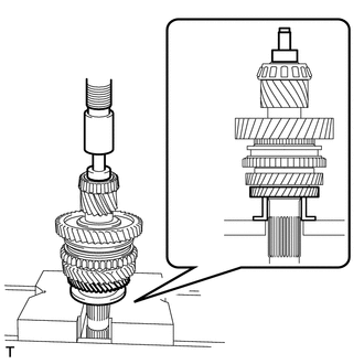
Using SST and a press, press the 3rd driven gear onto the output shaft.
- SST
- 09316-20011
09950-40011 (09957-04010)
09950-60010 (09951-00180, 09951-00340, 09952-06010)
33431C
14.INSTALL OUTPUT GEAR SPACER
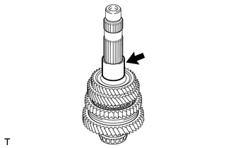
Install the output gear spacer to the output shaft.
33422B
15.INSTALL 4TH DRIVEN GEAR
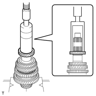
Using SST and a press, press the 4th driven gear onto the output shaft.
- SST
- 09316-60011 (09316-00011)
33428C
16.INSTALL 5TH DRIVEN GEAR
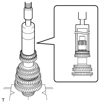
Using SST and a press, press the 5th driven gear onto the output shaft.
- SST
- 09316-60011 (09316-00011)
33431C
17.INSTALL OUTPUT GEAR SPACER
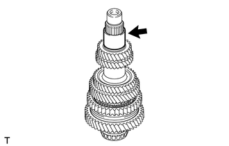
Install the output gear spacer to the output shaft.
33429B
18.INSTALL 6TH DRIVEN GEAR
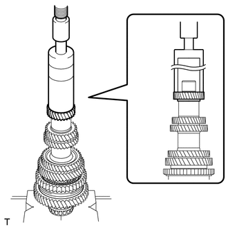
Using SST and a press, press the 6th driven gear onto the output shaft.
- SST
- 09316-60011 (09316-00011)
33321A
19.INSTALL REAR OUTPUT SHAFT BEARING
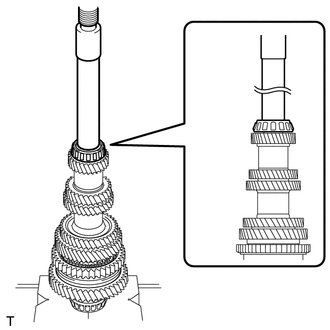
Using SST and a press, press a new rear output shaft bearing onto the output shaft.
- SST
- 09608-04031
20.INSPECT 2ND GEAR RADIAL CLEARANCE
21.INSPECT 1ST GEAR RADIAL CLEARANCE
22.INSPECT 2ND GEAR THRUST CLEARANCE
23.INSPECT 1ST GEAR THRUST CLEARANCE