THEFT DETERRENT / KEYLESS ENTRY THEFT DETERRENT SYSTEM Unlock Warning Switch Circuit
DESCRIPTION
The key unlock warning switch assembly comes on when the ignition key is inserted into the ignition key cylinder and goes off when the ignition key is removed.
WIRING DIAGRAM
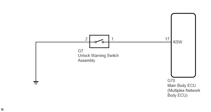
CAUTION / NOTICE / HINT
- NOTICE:
-
When replacing the main body ECU (multiplex network body ECU), make sure to replace it with a new one.
PROCEDURE
Connect the GTS to the DLC3.
Turn the ignition switch to ON.
Turn the GTS on.
Enter the following menus: Body / Main Body / Data List.
According to the display on the GTS, read the Data List.
- Body Electrical > Main Body > Data List
-
Tester Display Measurement Item Range Normal Condition Diagnostic Note Key Unlock Warning SW Unlock warning switch ON or OFF ON: Key is inserted into ignition key cylinder
OFF: Key is removed from ignition key cylinder-
- Body Electrical > Main Body > Data List
-
Tester Display Key Unlock Warning SW - 50003 123 32
- OK:
When the key is in the ignition key cylinder, "ON" appears on the screen.
- Result:
Proceed to OK NG
OK
Click hereVehicle Interior>THEFT DETERRENT / KEYLESS ENTRY>THEFT DETERRENT SYSTEM>PROBLEM SYMPTOMS TABLE
NG
Remove the unlock warning switch assembly.
Click hereVehicle Interior>DOOR LOCK>UNLOCK WARNING SWITCH>REMOVAL
Inspect the unlock warning switch assembly.
Click hereVehicle Interior>DOOR LOCK>UNLOCK WARNING SWITCH>INSPECTION
- Result:
Proceed to OK NG
OK
NG
Measure the resistance according to the value(s) in the table below.
- Standard Resistance:
Tester Connection Condition Specified Condition G78-17 (KSW) - G7-1 Always Below 1 Ω G78-17 (KSW) - Body ground Always 10 kΩ or higher G7-2 - Body ground Always Below 1 Ω G7-1 - Body ground Always 10 kΩ or higher
- Result:
Proceed to OK (for LHD) OK (for RHD) NG
OK (for LHD)
OK (for RHD)
NG