EA64F MANUAL TRANSMISSION / TRANSAXLE MANUAL TRANSAXLE ASSEMBLY INSTALLATION
PROCEDURE

 36100A
1.INSTALL TRANSFER AND TRANSAXLE SETTING STUD BOLT
Transfer Side:
Click hereDrivetrain>GF1A TRANSFER / 4WD / AWD>TRANSFER ASSEMBLY>REASSEMBLY
Clean the bolt holes.
Apply adhesive 1324 to 2 or 3 threads on one half of a new transfer and transaxle setting stud bolt A as shown in the illustration.
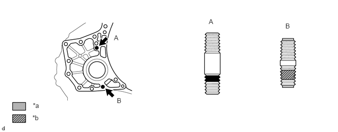
| *a | Toyota Genuine Adhesive 1324 | *b | Sealant |
- Adhesive:
Toyota Genuine Adhesive 1324, Three Bond 1324 or equivalent
- NOTICE:
- ·
Do not apply adhesive 1324 to the ends of the stud bolt.
·Install the stud bolt immediately after applying adhesive to prevent the adherence of foreign matter.
Install the 2 new transfer and transaxle setting stud bolts to the transaxle case positions shown in the illustration.
- Torque:
- 39.2 N*m (400 kgf*cm, 29 ft.*lbf)
- NOTICE:
-
Install the stud bolt so that the side that has sealant and adhesive is facing the automatic transaxle assembly.
- HINT:
-
Stud bolt length:
-
Stud bolt A: 69 mm (2.72 in.)
-
Stud bolt B: 47 mm (1.85 in.)
36100
2.INSTALL TRANSFER ASSEMBLY
3.INSTALL MANUAL TRANSAXLE ASSEMBLY
Align the input shaft with the clutch disc and install the manual transaxle assembly to the engine.
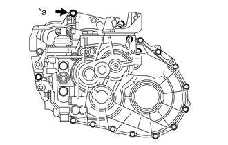
| *a | Temporarily |
Temporarily install the manual transaxle assembly with the bolt (*a).
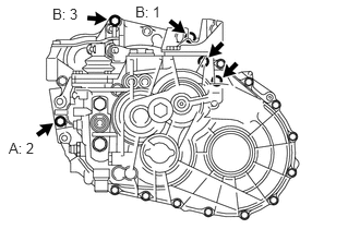
Tighten the 3 bolts labeled A and B in the order shown in the illustration, and then install the 2 bolts.
- Torque:
- for Bolt A : 46 N*m (469 kgf*cm, 34 ft.*lbf)
- for Bolt B : 64 N*m (653 kgf*cm, 47 ft.*lbf)
33119C
4.INSTALL STIFFENER PLATE LH
33118D
5.INSTALL STIFFENER PLATE RH
12156
6.INSTALL OIL PAN INSULATOR
12325A
7.INSTALL ENGINE MOUNTING BRACKET LH
- HINT:
-
Perform this procedure only when replacement of the engine mounting bracket LH is necessary.
Install the engine mounting bracket LH with the 4 bolts.
- Torque:
- 64 N*m (653 kgf*cm, 47 ft.*lbf)
12321A
8.INSTALL REAR ENGINE MOUNTING BRACKET
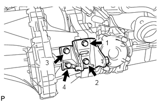
Install the rear engine mounting bracket with the 4 bolts in the order shown in the illustration.
- Torque:
- 45 N*m (459 kgf*cm, 33 ft.*lbf)
12311A
9.INSTALL FRONT ENGINE MOUNTING BRACKET
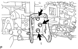
Temporarily install the rear engine mounting bracket with the 5 bolts.
Tighten the 3 bolts of the front engine mounting bracket in the order shown in the illustration.
- Torque:
- 64 N*m (653 kgf*cm, 47 ft.*lbf)
28100
10.INSTALL STARTER ASSEMBLY
11.INSTALL ENGINE ASSEMBLY WITH MANUAL TRANSAXLE
for 1AD-FTV:
Click hereEngine / Hybrid System>1AD-FTV ENGINE MECHANICAL>ENGINE ASSEMBLY>INSTALLATION
for 2AD-FTV:
Click hereEngine / Hybrid System>2AD-FTV ENGINE MECHANICAL>ENGINE ASSEMBLY>INSTALLATION