3ZR-FAE ENGINE CONTROL SFI SYSTEM P1055 VALVEMATIC Angle Difference (ECU)
DESCRIPTION
The VALVEMATIC system is able to continuously change the valve lift amount and valve timing. The VALVEMATIC system cooperates with the VVT-i to adjust the valve lift amount and valve timing optimally according to driving conditions. The ECM calculates the target intake air amount based on the amount the accelerator pedal is depressed and the engine speed to determine the value lift amount (duration), valve timing and throttle valve opening angle. The continuously variable valve lift controller assembly operates the actuator to adjust the duration to the duration requested by the ECM via CAN communication. The actual operating conditions are monitored by the sensors in the continuously variable valve lift controller assembly, which send the actual duration value to the ECM. The continuously variable valve lift controller assembly consists of the EDU, actuator, differential roller gear, angle sensor and position sensor.
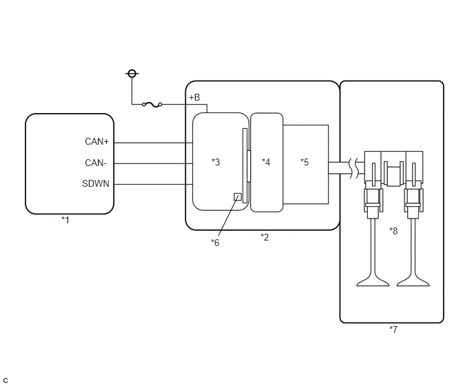
| *1 | ECM | *2 | Continuously Variable Valve Lift Controller |
| *3 | EDU | *4 | Actuator |
| *5 | Differential Roller Gear | *6 | Position Sensor and Angle Sensor |
| *7 | Engine | *8 | Continuously Variable Valve Train |
| DTC No. | Detection Item | DTC Detection Condition | Trouble Area | MIL | Memory |
|---|---|---|---|---|---|
| P1055 | VALVEMATIC Angle Difference (ECU) | The actual duration differs from the requested duration by 14.5°CA or more for a certain period of time (detected on the ECM side) (1 trip detection logic). | ·
Continuously variable valve lift controller assembly ·
Camshaft housing sub-assembly |
Comes on | DTC stored |
Perform the following procedures to confirm that the VALVEMATIC system is operating normally.
Connect the GTS to the DLC3.
Start the engine.
Turn the GTS on.
Enter the following menus: Powertrain / Engine and ECT / Active Test / Activate the VALVEMATIC (ENG ON) / All Data / VALVEMATIC Current Angle and VALVEMATIC Target Angle.
- NOTICE:
-
Make sure the following conditions are met when performing the Active Test.
- ·
The engine is running.
·The engine coolant temperature is 40°C (104°F) or higher.
·The vehicle is stationary.
·The shift lever is in P or N (neutral).
- Result:
The "VALVEMATIC Current Angle" follows the "VALVEMATIC Target Angle".
- HINT:
-
Perform a simulation test by referring to the engine coolant temperature and intake air temperature recorded in the freeze frame data.
-
When the Active Test results are abnormal, remove the continuously variable valve lift controller assembly from the camshaft housing and perform the "Activate the VALVEMATIC (ENG OFF)" Active Test with the removed continuously variable valve lift controller to determine whether the problem is with the continuously variable valve lift controller assembly or camshaft housing.
MONITOR DESCRIPTION
The VALVEMATIC system is monitored by the EDU in the continuously variable valve lift controller assembly and the ECM. When a VALVEMATIC system malfunction is detected, DTC P1055 is output.
CONFIRMATION DRIVING PATTERN
Connect the GTS to the DLC3.
Start the engine and warm it up.
Turn the GTS on.
Clear the DTCs (Click here Engine / Hybrid System>3ZR-FAE ENGINE CONTROL>SFI SYSTEM>DTC CHECK / CLEAR).
Turn the ignition switch off and wait for at least 30 seconds.
Start the engine and idle it for 20 seconds.
Turn the GTS on.
Clear the DTCs (Click here Engine / Hybrid System>3ZR-FAE ENGINE CONTROL>SFI SYSTEM>DTC CHECK / CLEAR).
Turn the ignition switch off and wait for at least 30 seconds.
Start the engine and idle it for 20 seconds.
Turn the ignition switch off and wait for at least 30 seconds.
Turn the ignition switch to ON.
Turn the GTS on.
Enter the following menus: Powertrain / Engine and ECT / Trouble Codes.
Read the DTCs.
CAUTION / NOTICE / HINT
- NOTICE:
-
When one of the following DTCs is output and the MIL is illuminated, actuator position learning is performed during the next trip. After the system returns to normal, actuator position learning is performed during the next trip and the MIL remains illuminated until learning is complete.
Actuator position learning is performed when these DTCs are output. P1049, P104A, P1055, P2646, P2647, P2648, P2649, P264A, U011B
- HINT:
- ·
After performing repairs, perform the confirmation driving pattern and check that DTCs are not output again.
·Read freeze frame data using the GTS. The ECM records vehicle and driving condition information as freeze frame data the moment a DTC is stored. When troubleshooting, freeze frame data can help determine if the vehicle was moving or stationary, if the engine was warmed up or not, if the air fuel ratio was lean or rich, and other data from the time the malfunction occurred.
·After using the GTS to perform minimum valve lift learning, keep the engine idling for 30 seconds to complete learning. Otherwise, the VALVEMATIC system may not operate normally, causing poor acceleration, etc.
PROCEDURE
Connect the GTS to the DLC3.
Turn the ignition switch to ON.
Turn the GTS on.
Enter the following menus: Powertrain / Engine and ECT / Trouble Codes.
- Powertrain > Engine and ECT > Trouble Codes
- 50001 234
Read the DTCs.
- Result:
Result Proceed to DTC P1055 is output A DTC P0112, P0113, P0115, P0117 or P0118 is output at same time as DTC P1055 B
- HINT:
- ·
If an engine coolant temperature sensor malfunction DTC or intake air temperature sensor malfunction DTC is output at the same time as DTC P1055, check the corresponding temperature sensor first.
·After repairing the temperature sensor, clear the DTCs, perform a simulation test and check that the temperature sensor DTC is not output.
·When the temperature sensor DTC does not reoccur but DTC P1055 is output again, perform troubleshooting from the next step. If a DTC is not output, troubleshooting is complete.
A
B
Remove the continuously variable valve lift controller assembly from the camshaft housing sub-assembly (Click here Engine / Hybrid System>3ZR-FAE ENGINE CONTROL>CONTINUOUSLY VARIABLE VALVE LIFT CONTROLLER>REMOVAL).
Connect the GTS to the DLC3.
Turn the ignition switch to ON.
Turn the GTS on.
Enter the following menus: Powertrain / Engine and ECT / Active Test / Activate the VALVEMATIC (ENG OFF) / All Data / VALVEMATIC Current Angle.
- Powertrain > Engine and ECT > Active Test
-
Active Test Display Activate the VALVEMATIC(ENG OFF) -
Data List Display VALVEMATIC Current Angle - 50004 234 164 162
When the continuously variable valve lift controller assembly is operated using the GTS, check whether the shaft moves (Click here Engine / Hybrid System>3ZR-FAE ENGINE CONTROL>SFI SYSTEM>DATA LIST / ACTIVE TEST).
- NOTICE:
- ·
Make sure to perform the "Activate the VALVEMATIC (ENG OFF)" Active Test with the continuously variable valve lift controller assembly removed from the vehicle.
·Perform the Active Test with the body of the continuously variable valve lift controller assembly connected to ground, as the continuously variable valve lift controller assembly is grounded through the body.
- Result:
Tester Operation Specified Condition Low VALVEMATIC Current Angle is 100 to 120 deg(CA) and shaft extends High VALVEMATIC Current Angle is 250 deg(CA) or more and shaft retracts
- HINT:
- ·
If the malfunction does not reoccur, refer to the engine coolant temperature and intake air temperature recorded in the freeze frame data and perform a simulation test.
·Perform "Inspection After Repair" after replacing the camshaft housing sub-assembly or continuously variable valve lift controller assembly (Click here Engine / Hybrid System>3ZR-FAE ENGINE CONTROL>SFI SYSTEM>INITIALIZATION).
- Result:
Proceed to OK NG
OK
NG
(Click here Engine / Hybrid System>3ZR-FAE ENGINE CONTROL>CONTINUOUSLY VARIABLE VALVE LIFT CONTROLLER>REMOVAL)