K114 MULTIDRIVE / CVT OIL COOLER INSTALLATION
PROCEDURE

 32913F
1.INSTALL TRANSMISSION OIL COOLER BRACKET
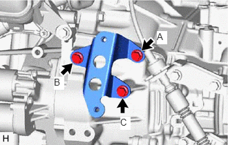
Install the transmission oil cooler bracket to the continuously variable transaxle assembly with the 3 bolts.
- Torque:
- 13.5 N*m (138 kgf*cm, 10 ft.*lbf)
- NOTICE:
-
Tightening order: Temporarily install bolt (A) → Tighten bolt (B) → Tighten bolt (C) → Tighten bolt (A)
33493B
2.INSTALL OIL COOLER
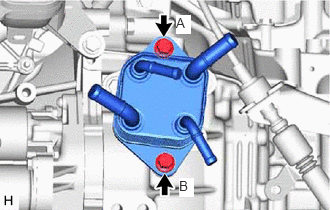
Install the oil cooler to the transmission oil cooler bracket with the 2 bolts.
- Torque:
- 13.5 N*m (138 kgf*cm, 10 ft.*lbf)
- NOTICE:
-
Tightening order: Temporarily install bolt (A) → Tighten bolt (B) → Tighten bolt (A)
32943S
3.CONNECT NO. 1 TRANSMISSION OIL COOLER HOSE
Connect the No. 1 transmission oil cooler hose to the oil cooler, and slide the clip to secure the hose.
- NOTICE:
- ·
Align each paint mark on the No. 1 transmission oil cooler hose with each one on the oil cooler.
·Fully insert the No. 1 transmission oil cooler hose to the 2nd rib on each oil cooler pipe.
32943U
4.CONNECT NO. 2 TRANSMISSION OIL COOLER HOSE
Connect the No. 2 transmission oil cooler hose to the oil cooler, and slide the clip to secure the hose.
- NOTICE:
- ·
Align each paint mark on the No. 2 transmission oil cooler hose with each one on the oil cooler.
·Fully insert the No. 2 transmission oil cooler hose to the 2nd rib on each oil cooler pipe.
16267
5.CONNECT NO. 3 WATER BY-PASS HOSE
Connect the No. 3 water by-pass hose to the oil cooler, and slide the clip to secure the hose.
- NOTICE:
- ·
Align each paint mark on the No. 3 water by-pass hose with each one on the oil cooler.
·Fully insert the No. 3 water by-pass hose to the 2nd rib on each oil cooler pipe.
16282
6.CONNECT NO. 5 WATER BY-PASS HOSE
Connect the No. 5 water by-pass hose to the oil cooler, and slide the clip to secure the hose.
- NOTICE:
- ·
Align each paint mark on the No. 5 water by-pass hose with each one on the oil cooler.
·Fully insert the No. 5 water by-pass hose to the 2nd rib on each oil cooler pipe.
7.ADD ENGINE COOLANT
8.INSPECT FOR COOLANT LEAK
9.ADD CONTINUOUSLY VARIABLE TRANSAXLE FLUID
10.INSPECT FOR FLUID LEAK
51444
11.INSTALL REAR ENGINE UNDER COVER LH
51441
12.INSTALL NO. 1 ENGINE UNDER COVER