Home › Audio / Visual / Telematics › NAVIGATION / MULTI INFO DISPLAY › NAVIGATION SYSTEM(for SD) › 2015.10–2016.08
RM3090E _56 Audio / Visual / Telematics _008776 NAVIGATION / MULTI INFO DISPLAY _0104513 NAVIGATION SYSTEM(for SD) J

NAVIGATION / MULTI INFO DISPLAY  NAVIGATION SYSTEM(for SD)  Microphone Circuit between Microphone and Navigation Receiver Assembly  


DESCRIPTION

This circuit sends a microphone signal from the telephone microphone assembly to the navigation receiver assembly.

It also supplies power from the navigation receiver assembly to the telephone microphone assembly.

WIRING DIAGRAM
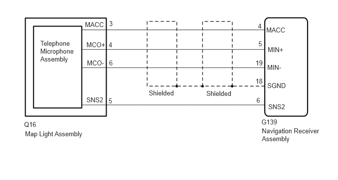
E280091E10
0.854,0.833 1.604,1.365 0.75,0.531 10 false Telephone Microphone Assembly 1.802,0.438 2.344,0.646 0.542,0.208 10 false MACC 1.833,2.031 2.344,2.25 0.51,0.219 10 false SNS2 1.833,0.865 2.365,1.073 0.531,0.208 10 false MCO+ 1.844,1.25 2.76,1.458 0.917,0.208 10 false MCO- 2.313,0.417 2.823,0.635 0.51,0.219 10 false 3 2.302,0.865 2.813,1.083 0.51,0.219 10 false 4 2.313,1.25 2.823,1.469 0.51,0.219 10 false 6 2.302,2.052 2.813,2.271 0.51,0.219 10 false 5 0.51,2.552 1.021,2.771 0.51,0.219 10 false Q16 0.531,2.75 2.573,3.01 2.042,0.26 10 false Map Light Assembly 5.469,0.469 5.719,0.635 0.25,0.167 10 false 4 5.479,0.844 5.729,1.01 0.25,0.167 10 false 5 5.417,1.25 5.667,1.417 0.25,0.167 10 false 19 5.417,1.635 5.667,1.802 0.25,0.167 10 false 18 5.438,2.042 5.688,2.208 0.25,0.167 10 false 6 5.646,0.552 6.26,0.729 0.615,0.177 10 false MACC 5.677,0.969 6.292,1.146 0.615,0.177 10 false MIN+ 5.667,1.344 6.281,1.521 0.615,0.177 10 false MIN- 5.667,1.729 6.281,1.906 0.615,0.177 10 false SGND 5.688,2.177 6.302,2.354 0.615,0.177 10 false SNS2 5.542,2.5 6.156,2.677 0.615,0.177 10 false G139 5.552,2.688 6.813,3.01 1.26,0.323 10 false Navigation Receiver Assembly 3.156,1.885 3.771,2.063 0.615,0.177 10 false Shielded 4.375,1.896 4.99,2.073 0.615,0.177 10 false Shielded

CAUTION / NOTICE / HINT

NOTICE:

Check that the wire harness is properly installed and does not have any sharp bends, pinching or loose connections.

Click hereGeneral>INTRODUCTION>HOW TO TROUBLESHOOT ECU CONTROLLED SYSTEMS>HOW TO PROCEED WITH TROUBLESHOOTING


PROCEDURE
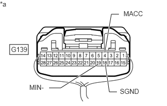
1.CHECK NAVIGATION RECEIVER ASSEMBLY
a.
E280108C07
0.198,0.917 0.583,1.125 0.385,0.208 2.021,1.323 1.25,1.813 1.25,1.813 1.01,1.813 true 2.167,1.333 2.25,1.896 2.25,1.896 2.406,1.896 true 2.156,1.083 2.292,0.292 2.292,0.292 2.448,0.292 true 0,0 0.313,0.156 0.313,0.156 10 false *a 0.229,0.938 0.583,1.135 0.354,0.198 10 false G139 0.604,1.719 0.958,1.917 0.354,0.198 10 false MIN- 2.469,1.802 3.135,1.979 0.667,0.177 10 false SGND 2.542,0.198 3.031,0.365 0.49,0.167 10 false MACC
*a Component with harness connected
(Navigation Receiver Assembly)


Measure the resistance according to the value(s) in the table below.

Standard Resistance:
Tester Connection Condition Specified Condition
G139-19 (MIN-) - Body ground Always Below 1 Ω
G139-18 (SGND) - Body ground Always Below 1 Ω


b.

Measure the voltage according to the value(s) in the table below.

Standard Voltage:
Tester Connection Switch Condition Specified Condition
G139-4 (MACC) - Body ground Engine switch on (ACC) 4.75 to 5.25 V


Result:
Proceed to
OK
NG


OK

2.CHECK HARNESS AND CONNECTOR (NAVIGATION RECEIVER ASSEMBLY - MAP LIGHT ASSEMBLY)

NG

2.CHECK HARNESS AND CONNECTOR (NAVIGATION RECEIVER ASSEMBLY - MAP LIGHT ASSEMBLY)
a.

Disconnect the G139 navigation receiver assembly connector.


b.

Disconnect the Q16 map light assembly connector.


c.

Measure the resistance according to the value(s) in the table below.

Standard Resistance:
Tester Connection Condition Specified Condition
G139-4 (MACC) - Q16-3 (MACC) Always Below 1 Ω
G139-5 (MIN+) - Q16-4 (MCO+) Always Below 1 Ω
G139-19 (MIN-) - Q16-6 (MCO-) Always Below 1 Ω
G139-6 (SNS2) - Q16-5 (SNS2) Always Below 1 Ω
G139-4 (MACC) - Body ground Always 10 kΩ or higher
G139-5 (MIN+) - Body ground Always 10 kΩ or higher
G139-19 (MIN-) - Body ground Always 10 kΩ or higher
G139-18 (SGND) - Body ground Always 10 kΩ or higher
G139-6 (SNS2) - Body ground Always 10 kΩ or higher


Result:
Proceed to
OK
NG


OK

3.CHECK TELEPHONE MICROPHONE ASSEMBLY

NG

REPAIR OR REPLACE HARNESS OR CONNECTOR

3.CHECK TELEPHONE MICROPHONE ASSEMBLY
a.

Replace the telephone microphone assembly with a known good.

Click hereAudio / Visual / Telematics>AUDIO / VIDEO>AMPLIFIER MICROPHONE ASSEMBLY>REMOVAL


b.

Check if the same problem occurs again.

OK:

Malfunction disappears.


Result:
Proceed to
OK
NG


OK

END (TELEPHONE MICROPHONE ASSEMBLY IS DEFECTIVE)

NG

REPLACE MAP LIGHT ASSEMBLY