Home › Engine / Hybrid System › STOP AND START › STOP AND START SYSTEM(for 3ZR-FAE) › from 2015.10
RM3090E _51 Engine / Hybrid System _009049 STOP AND START _0166176 STOP AND START SYSTEM(for 3ZR-FAE) J

STOP AND START  STOP AND START SYSTEM(for 3ZR-FAE)  Neutral Position Switch Circuit  


DESCRIPTION

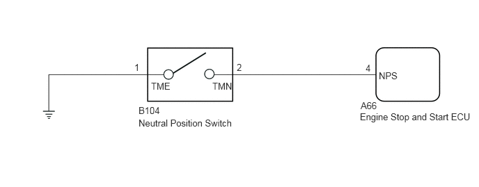
The neutral position switch detects whether the shift lever is in neutral. When the shift lever in any position other than neutral, stop and start control is prohibited. (for Manual Transaxle)

The engine stop and start ECU uses the park/neutral position switch assembly installed to the continuously variable transaxle assembly to detect when the shift lever is in P or N. (for CVT)

WIRING DIAGRAM

for CVT:
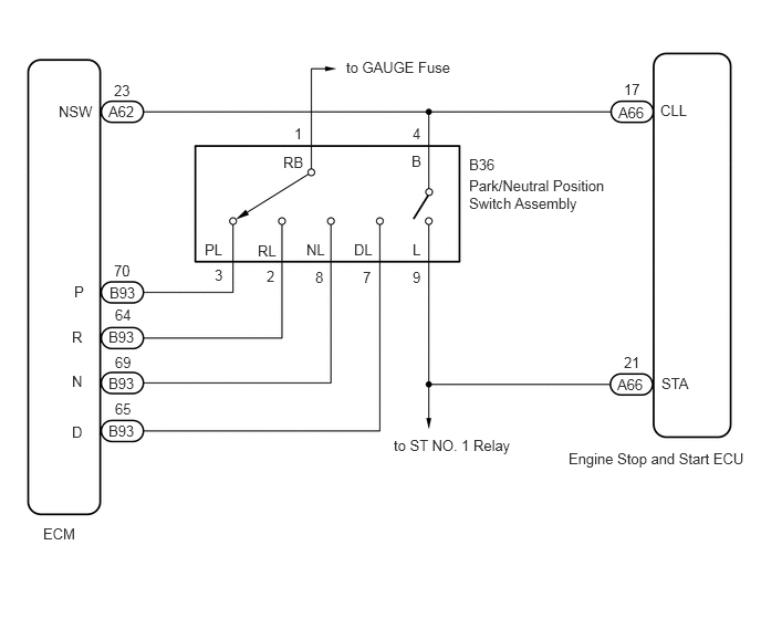

A348495E09
4.417,1.667 5.781,2.25 1.365,0.583 10 false Park/Neutral Position Switch Assembly 4.417,1.469 4.875,1.667 0.458,0.198 10 false B36 3.885,1.177 4.042,1.375 0.156,0.198 10 false 4 3.875,1.438 4.031,1.635 0.156,0.198 10 false B 3.885,2.271 4.042,2.469 0.156,0.198 10 false L 3.885,2.531 4.042,2.729 0.156,0.198 10 false 9 3.333,2.271 3.646,2.469 0.313,0.198 10 false DL 3.417,2.531 3.573,2.729 0.156,0.198 10 false 7 2.885,2.271 3.198,2.469 0.313,0.198 10 false NL 2.969,2.531 3.125,2.729 0.156,0.198 10 false 8 3.708,4.115 4.969,4.344 1.26,0.229 10 false to ST NO. 1 Relay 5.354,4.24 7.125,4.479 1.771,0.24 10 false Engine Stop and Start ECU 3.26,0.552 4.656,0.771 1.396,0.219 10 false to GAUGE Fuse 0.552,0.969 1.01,1.167 0.458,0.198 10 false NSW 1.021,0.969 1.479,1.167 0.458,0.198 10 false A62 1.073,0.771 1.385,0.969 0.313,0.198 10 false 23 2.427,2.281 2.74,2.479 0.313,0.198 10 false RL 2.51,2.521 2.667,2.719 0.156,0.198 10 false 2 1.927,2.271 2.24,2.469 0.313,0.198 10 false PL 2.021,2.51 2.177,2.708 0.156,0.198 10 false 3 2.667,1.448 2.979,1.646 0.313,0.198 10 false RB 2.771,1.177 2.927,1.375 0.156,0.198 10 false 1 0.698,2.667 0.917,2.865 0.219,0.198 10 false P 1.031,2.677 1.49,2.875 0.458,0.198 10 false B93 1.073,2.469 1.385,2.667 0.313,0.198 10 false 70 0.677,3.094 0.896,3.292 0.219,0.198 10 false R 0.677,3.51 0.896,3.708 0.219,0.198 10 false N 0.677,3.99 0.896,4.188 0.219,0.198 10 false D 1.021,3.979 1.479,4.177 0.458,0.198 10 false B93 1.021,3.531 1.479,3.729 0.458,0.198 10 false B93 1.021,3.094 1.479,3.292 0.458,0.198 10 false B93 1.083,2.885 1.396,3.083 0.313,0.198 10 false 64 1.083,3.333 1.396,3.531 0.313,0.198 10 false 69 1.083,3.771 1.396,3.969 0.313,0.198 10 false 65 5.813,3.542 6.271,3.74 0.458,0.198 10 false A66 5.875,3.333 6.188,3.531 0.313,0.198 10 false 21 6.229,3.531 6.688,3.729 0.458,0.198 10 false STA 5.823,0.979 6.281,1.177 0.458,0.198 10 false A66 6.219,0.958 6.677,1.156 0.458,0.198 10 false CLL 5.875,0.76 6.188,0.958 0.313,0.198 10 false 17 0.406,4.948 0.865,5.146 0.458,0.198 10 false ECM


for Manual Transaxle:


A348170E14
2.073,1.573 2.531,1.771 0.458,0.198 10 false B104 2.01,0.927 2.469,1.125 0.458,0.198 10 false 1 3.542,0.927 4,1.125 0.458,0.198 10 false 2 2.073,1.76 4.333,2.094 2.26,0.333 10 false Neutral Position Switch 5.469,0.938 5.927,1.135 0.458,0.198 10 false 4 5.396,1.5 5.854,1.698 0.458,0.198 10 false A66 5.385,1.667 7.104,1.896 1.719,0.229 10 false Engine Stop and Start ECU 5.667,1.052 6.125,1.25 0.458,0.198 10 false NPS 3.177,1.208 3.635,1.406 0.458,0.198 10 false TMN 2.26,1.208 2.719,1.406 0.458,0.198 10 false TME


PROCEDURE

1.CONFIRM MODEL
a.

Choose the model to be inspected.


Result:
Result Proceed to
for CVT A
for Manual Transaxle B


A

2.READ VALUE USING GTS (NEUTRAL SWITCH)

B

5.READ VALUE USING GTS (NEUTRAL SWITCH)
2.READ VALUE USING GTS (NEUTRAL SWITCH)
a.

Connect the GTS to the DLC3.


b.

Turn the ignition switch to ON.


c.

Turn the GTS on.


d.

Enter the following menus: Powertrain / Stop and Start / Data List / Neutral Switch.


e.

In accordance with the display on the GTS, read the Data List.

Powertrain > Stop and Start > Data List
Tester Display
Neutral Switch
50003 227 9
OK:
Tester Display Condition Normal Condition
Neutral Switch Shift lever in P or N ON
Shift lever not in P or N OFF


Result:
Proceed to
OK
NG


OK

PROCEED TO NEXT SUSPECTED AREA SHOWN IN PROBLEM SYMPTOMS TABLE

NG

3.INSPECT PARK/NEUTRAL POSITION SWITCH ASSEMBLY
a.

Inspect the park/neutral position switch assembly.

Click hereDrivetrain>K114F MULTIDRIVE / CVT>PARK / NEUTRAL POSITION SWITCH>INSPECTION


Result:
Proceed to
OK
NG


OK

4.CHECK HARNESS AND CONNECTOR (ENGINE STOP AND START ECU - PARK/NEUTRAL POSITION SWITCH ASSEMBLY)

NG

REPLACE PARK/NEUTRAL POSITION SWITCH ASSEMBLY

4.CHECK HARNESS AND CONNECTOR (ENGINE STOP AND START ECU - PARK/NEUTRAL POSITION SWITCH ASSEMBLY)
a.

Disconnect the A66 engine stop and start ECU connector.


b.

Disconnect the B36 park/neutral position switch assembly connector.


c.

Measure the resistance according to the value(s) in the table below.

Standard Resistance:
Tester Connection Condition Specified Condition
A66-21 (STA) - B36-9 (L) Always Below 1 Ω
A66-17 (CLL) - B36-4 (B) Always Below 1 Ω
A66-21 (STA) - Body ground Always 80 to 180 Ω
A66-17 (CLL) - Body ground Always 10 kΩ or higher
B36-9 (L) - Body ground Always 80 to 180 Ω
B36-4 (B) - Body ground Always 10 kΩ or higher


Result:
Proceed to
OK
NG


OK

NG

REPAIR OR REPLACE HARNESS OR CONNECTOR

5.READ VALUE USING GTS (NEUTRAL SWITCH)
a.

Connect the GTS to the DLC3.


b.

Turn the ignition switch to ON.


c.

Turn the GTS on.


d.

Enter the following menus: Powertrain / Stop and Start / Data List / Neutral Switch.

Powertrain > Stop and Start > Data List
Tester Display
Neutral Switch
50003 227 9

e.

Read the value when the shift lever is in neutral and any other position

OK:
Tester Display Condition Normal Condition
Neutral Switch Shift lever is in neutral ON
Shift lever is in any position other than neutral OFF


Result:
Proceed to
OK
NG


OK

PROCEED TO NEXT SUSPECTED AREA SHOWN IN PROBLEM SYMPTOMS TABLE

NG

6.CHECK HARNESS AND CONNECTOR (ENGINE STOP AND START ECU - NEUTRAL POSITION SWITCH)
a.

Disconnect the A36 engine stop and start ECU connector.


b.

Disconnect the B104 neutral position switch connector.


c.

Measure the resistance according to the value(s) in the table below.

Standard Resistance:
Tester Connection Condition Specified Condition
A36-4 (NPS) - B104-2 (TMN) Always Below 1 Ω
B104-1 (TME) - Body ground Always Below 1 Ω
A36-4 (NPS) - Body ground Always 10 kΩ or higher
B104-2 (TMN) - Body ground Always 10 kΩ or higher


Result:
Proceed to
OK
NG


OK

7.INSPECT NEUTRAL POSITION SWITCH ASSEMBLY

NG

REPAIR OR REPLACE HARNESS OR CONNECTOR

7.INSPECT NEUTRAL POSITION SWITCH ASSEMBLY
a.

Inspect the neutral position switch assembly.

Click hereDrivetrain>EB61F MANUAL TRANSMISSION / TRANSAXLE>NEUTRAL POSITION SWITCH>INSPECTION


Result:
Proceed to
OK
NG


OK

PROCEED TO NEXT SUSPECTED AREA SHOWN IN PROBLEM SYMPTOMS TABLE

NG