RM3090E
_59
Vehicle Exterior
_008794
DOOR / HATCH
_0280890
KICK SENSOR
A
DOOR / HATCH KICK SENSOR INSTALLATION
PROCEDURE

 891B2
1.INSTALL KICK DOOR CONTROL SENSOR
a.
2.479,1.042 3,1.042
true
1.979,1.667 2,2
2,2 2.167,2
true
0.75,1.167 0.917,1.167
0.917,1.167 1.667,1.5
true
1.75,0.25 1.917,0.25
1.917,0.25 2,1.25
true
3.083,0.958 3.333,1.115
0.25,0.156
10
true
*a
0.5,1.083 0.75,1.25
0.25,0.167
10
true
*b
2.25,1.917 2.5,2.073
0.25,0.156
10
true
*a
1.5,0.167 1.75,0.333
0.25,0.167
10
true
*b
1.354,1.083 1.563,1.25
0.208,0.167
10
true
(1)
0.958,0.417 1.167,0.583
0.208,0.167
10
true
(2)
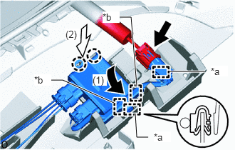
| *a | Clamp |
| *b | Guide |
Insert the 2 guides as indicated by the arrows in the order shown in the illustration.
b.
Attach the 2 claws.
c.
Attach the 2 clamps.
d.
Connect the connector.
e.
1.833,1 2.417,1.917
2.417,1.917 2.667,1.917
true
1.583,0.917 1,0.167
1,0.167 0.75,0.167
true
0.521,0.094 0.833,0.25
0.313,0.156
10
false
*a
2.75,1.833 3.063,1.99
0.313,0.156
10
false
*b
2.188,0.01 2.292,0.177
0.104,0.167
10
true
1
1.583,0.25 1.677,0.417
0.094,0.167
10
true
2
1.083,0.51 1.188,0.667
0.104,0.156
10
true
3
0.5,0.844 0.594,1
0.094,0.156
10
true
4
0.104,1.167 0.198,1.333
0.094,0.167
10
true
5
2.76,0.917 2.906,1.073
0.146,0.156
10
true
6
2.271,1.177 2.417,1.333
0.146,0.156
10
true
7
1.833,1.51 1.979,1.667
0.146,0.156
10
true
8
1.271,1.833 1.417,1.99
0.146,0.156
10
true
9
0.917,2 1.167,2.177
0.25,0.177
10
true
10
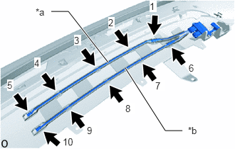
| *a | Antenna Upper |
| *b | Antenna Lower |
Attach the 10 claws in the order shown in the illustration to install the kick door control sensor.
- NOTICE:
- ·
Install the kick door control sensor so that antenna line does not protrude from the groove.
·Make sure that the antenna line does not cross over the edge of the connector.
52159
2.INSTALL REAR BUMPER COVER
3. CHECK TOUCHLESS POWER BACK DOOR OPENING OPERATION