Home › Vehicle Interior › SEAT › FRONT POWER SEAT CONTROL SYSTEM(w/ Memory) › from 2016.08
RM3090E _58 Vehicle Interior _008433 SEAT _0062871 FRONT POWER SEAT CONTROL SYSTEM(w/ Memory) J

SEAT  FRONT POWER SEAT CONTROL SYSTEM(w/ Memory)  Front Power Seat does not Operate with Front Power Seat Switch  


DESCRIPTION

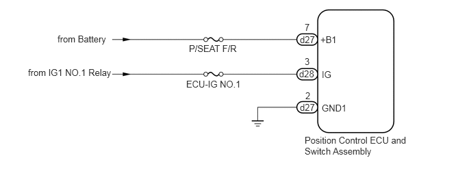
Signals are input into the position control ECU and switch assembly. The built-in ECU manages the signals received from the power seat switch assembly and operates each motor. If the position control ECU and switch assembly receives more than 2 motor operation signals, the motor is stopped. Manual operation is restarted after the position control ECU and switch assembly receives 1 signal only.

WIRING DIAGRAM
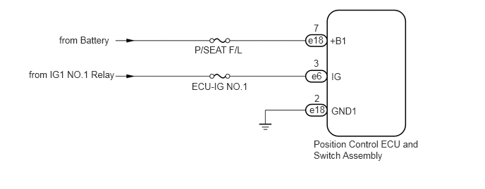
for LHD:
B359786E03
0.875,0.51 1.792,0.708 0.917,0.198 10 false from Battery 0.427,1.021 1.813,1.26 1.385,0.24 10 false from IG1 NO.1 Relay 2.875,0.656 3.792,0.854 0.917,0.198 10 false P/SEAT F/L 2.833,1.198 3.75,1.396 0.917,0.198 10 false ECU-IG NO.1 4.552,0.51 4.854,0.698 0.302,0.188 10 false e18 4.604,1.042 4.906,1.229 0.302,0.188 10 false e6 4.573,1.542 4.875,1.729 0.302,0.188 10 false e18 4.635,0.333 4.938,0.521 0.302,0.188 10 false 7 4.635,0.854 4.938,1.042 0.302,0.188 10 false 3 4.646,1.375 4.948,1.563 0.302,0.188 10 false 2 4.875,0.521 5.177,0.708 0.302,0.188 10 false +B1 4.896,1.052 5.198,1.24 0.302,0.188 10 false IG 4.896,1.563 5.406,1.76 0.51,0.198 10 false GND1 4.635,2.052 6.229,2.49 1.594,0.438 10 false Position Control ECU and Switch Assembly

for RHD:
B359786E04
0.875,0.51 1.792,0.708 0.917,0.198 10 false from Battery 0.427,1.021 1.813,1.26 1.385,0.24 10 false from IG1 NO.1 Relay 2.875,0.656 3.792,0.854 0.917,0.198 10 false P/SEAT F/R 2.833,1.198 3.75,1.396 0.917,0.198 10 false ECU-IG NO.1 4.563,0.521 4.865,0.708 0.302,0.188 10 false d27 4.552,1.042 4.854,1.229 0.302,0.188 10 false d28 4.563,1.552 4.865,1.74 0.302,0.188 10 false d27 4.635,0.333 4.938,0.521 0.302,0.188 10 false 7 4.635,0.854 4.938,1.042 0.302,0.188 10 false 3 4.646,1.375 4.948,1.563 0.302,0.188 10 false 2 4.875,0.521 5.177,0.708 0.302,0.188 10 false +B1 4.896,1.052 5.198,1.24 0.302,0.188 10 false IG 4.896,1.563 5.51,1.75 0.615,0.188 10 false GND1 4.635,2.052 6.229,2.49 1.594,0.438 10 false Position Control ECU and Switch Assembly

CAUTION / NOTICE / HINT

NOTICE:

Inspect the fuses for circuits related to this system before performing the following procedure.


PROCEDURE

1.CHECK FRONT POWER SEAT OPERATION
a.

Check that each function of the power seat operates normally by using the power seat switch assembly.

Click hereVehicle Interior>SEAT>FRONT POWER SEAT CONTROL SYSTEM(w/ Memory)>OPERATION CHECK


Result:
Result Proceed to
All power seat functions do not operate A
One or more power seat functions do not operate B


A

2.CHECK HARNESS AND CONNECTOR (POSITION CONTROL ECU AND SWITCH ASSEMBLY - BATTERY AND BODY GROUND)

B

GO TO OTHER DIAGNOSIS PROCEDURE (One or more Power Seat Motors do not Operate)

2.CHECK HARNESS AND CONNECTOR (POSITION CONTROL ECU AND SWITCH ASSEMBLY - BATTERY AND BODY GROUND)
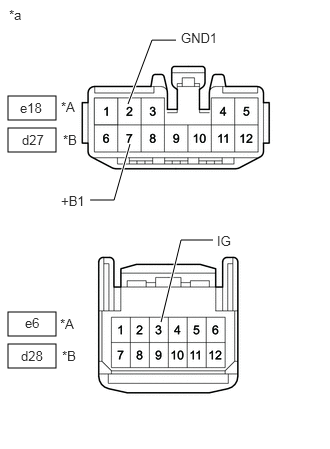
a.
B359787C16
0.083,1 0.583,1.25 0.5,0.25 0.083,3.25 0.583,3.5 0.5,0.25 0.083,1.333 0.583,1.583 0.5,0.25 0.083,3.583 0.583,3.833 0.5,0.25 1.354,1.5 1.188,2.083 1.188,2.083 0.938,2.083 true 1.333,1.083 1.583,0.417 1.583,0.417 1.833,0.417 true 1.677,3.354 1.885,2.5 1.885,2.5 2.219,2.5 true 0.094,0.073 0.406,0.229 0.313,0.156 10 false *a 0.208,1.042 0.521,1.24 0.313,0.198 10 false e18 0.26,3.281 0.573,3.479 0.313,0.198 10 false e6 0.635,2.01 1.01,2.229 0.375,0.219 10 false +B1 1.885,0.313 2.344,0.479 0.458,0.167 10 false GND1 2.26,2.427 2.594,2.594 0.333,0.167 10 false IG 0.635,1.031 0.948,1.229 0.313,0.198 10 false *A 0.229,1.375 0.542,1.573 0.313,0.198 10 false d27 0.656,1.375 0.969,1.573 0.313,0.198 10 false *B 0.625,3.292 0.938,3.49 0.313,0.198 10 false *A 0.219,3.625 0.531,3.823 0.313,0.198 10 false d28 0.646,3.625 0.958,3.823 0.313,0.198 10 false *B
*A for LHD
*B for RHD
*a Front view of wire harness connector
(to Position Control ECU and Switch Assembly)


Disconnect the position control ECU and switch assembly connector.


b.

Measure the resistance according to the value(s) in the table below.

Standard Resistance:
for LHD:
Tester Connection Condition Specified Condition
e18-2 (GND1) - Body ground Always Below 1 Ω

for RHD:
Tester Connection Condition Specified Condition
d27-2 (GND1) - Body ground Always Below 1 Ω


c.

Measure the voltage according to the value(s) in the table below.

Standard Voltage:
for LHD:
Tester Connection Condition Specified Condition
e18-7 (+B1) - Body ground Always 11 to 14 V
e6-3 (IG) - Body ground Ignition switch off Below 1 V
Ignition switch ON 11 to 14 V

for RHD:
Tester Connection Condition Specified Condition
d27-7 (+B1) - Body ground Always 11 to 14 V
d28-3 (IG) - Body ground Ignition switch off Below 1 V
Ignition switch ON 11 to 14 V


Result:
Proceed to
OK
NG


OK

REPLACE POSITION CONTROL ECU AND SWITCH ASSEMBLY

NG

REPAIR OR REPLACE HARNESS OR CONNECTOR