A25A-FXS EMISSION CONTROL FUEL TANK PRESSURE SENSOR(w/ Canister Pump Module) INSTALLATION
PROCEDURE

 89461
1.INSTALL FUEL TANK PRESSURE SENSOR (VAPOR PRESSURE SENSOR)
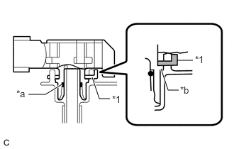
| *1 | Tube Joint Clip |
| *a | O-ring |
| *b | Collar |
Push the fuel tank pressure sensor (vapor pressure sensor) onto the fuel tank assembly, then install the tube joint clip.
- NOTICE:
- ·
Check that there are no scratches or foreign matter around the connecting parts of the fuel tank pressure sensor (vapor pressure sensor) and fuel suction plate sub-assembly before performing this work.
·Check that the fuel suction plate sub-assembly is securely inserted to the end of the fuel tank pressure sensor (vapor pressure sensor).
·Check that the tube joint clip is on the collar of the fuel tank pressure sensor (vapor pressure sensor).
·After installing the tube joint clip, check that the fuel tank pressure sensor (vapor pressure sensor) cannot be pulled out.
Connect the fuel tank pressure sensor (vapor pressure sensor) connector.
58325E
2.INSTALL REAR FLOOR SERVICE HOLE COVER
58903A
3.INSTALL CONSOLE REAR END PANEL SUB-ASSEMBLY