RM3620E
_59
Vehicle Exterior
_076526
SLIDING ROOF / CONVERTIBLE
_0372465
SLIDING ROOF SYSTEM
U
SLIDING ROOF / CONVERTIBLE SLIDING ROOF SYSTEM TERMINALS OF ECU
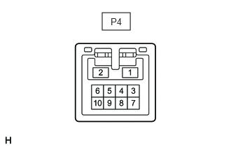
CHECK SLIDING ROOF ECU (SLIDING ROOF DRIVE GEAR SUB-ASSEMBLY)
1.521,0.188 1.938,0.448
0.417,0.26
1.646,0.24 2.104,0.438
0.458,0.198
10
false
P4
a.
Disconnect the P4 sliding roof ECU (sliding roof drive gear sub-assembly) connector.
b.
Measure the resistance and voltage according to the value(s) in the table below.
| Terminal No. (Symbol) | Wiring Color | Terminal Description | Condition | Specified Condition |
|---|---|---|---|---|
| P4-1 (B) - P4-2 (E) | W - W-B | Battery power supply | Ignition switch off | 11 to 14 V |
| P4-2 (E) - Body ground | W-B - Body ground | Ground | Always | Below 1 Ω |
c.
Reconnect the P4 sliding roof ECU (sliding roof drive gear sub-assembly) connector.
d.
Measure the voltage according to the value(s) in the table below.
| Terminal No. (Symbol) | Wiring Color | Terminal Description | Condition | Specified Condition |
|---|---|---|---|---|
| P4-5 (UP) - Body ground | GR - Body ground | Tilt switch (UP) signal | Ignition switch ON, UP switch on the tilt switch off → on | 11 to 14 V → Below 1 V |
| P4-8 (CLS) - Body ground | SB - Body ground | Slide switch (CLOSE) signal | Ignition switch ON, CLOSE switch on the slide switch off → on | 11 to 14 V → Below 1 V |
| P4-9 (DWN) - Body ground | LG - Body ground | Tilt switch (DOWN) signal | Ignition switch ON, DOWN switch on the tilt switch off → on | 11 to 14 V → Below 1 V |
| P4-10 (OPN) - Body ground | L - Body ground | Slide switch (OPEN) signal | Ignition switch ON, OPEN switch on the slide switch off → on | 11 to 14 V → Below 1 V |
e.
Measure the pulse according to the value(s) in the table below.
| Terminal No. (Symbol) | Wiring Color | Terminal Description | Condition | Specified Condition |
|---|---|---|---|---|
| P4-7 (MPX1) - Body ground | P - Body ground | LIN communication line | Ignition switch ON | Pulse generation |
CHECK INSTRUMENT PANEL JUNCTION BLOCK ASSEMBLY AND MAIN BODY ECU (MULTIPLEX NETWORK BODY ECU)
Click hereVehicle Exterior>WINDOW / GLASS>POWER WINDOW CONTROL SYSTEM>TERMINALS OF ECU