A25A-FKS COOLING THERMOSTAT INSTALLATION
CAUTION / NOTICE / HINT
- NOTICE:
-
This procedure includes the removal of small-head bolts. Refer to Small-Head Bolts of Basic Repair Hint to identify the small-head bolts.
-
Click hereGeneral>INTRODUCTION>REPAIR INSTRUCTION>PRECAUTION
PROCEDURE

 16031
1.INSTALL WATER INLET WITH THERMOSTAT SUB-ASSEMBLY
Install a new gasket to the water inlet with thermostat sub-assembly.
- HINT:
-
Be sure to clean the contact surfaces.
Using an 8 mm socket wrench, install the water inlet with thermostat sub-assembly with the 2 bolts.
- Torque:
- 10 N*m (102 kgf*cm, 7 ft.*lbf)
Connect the No. 7 water by-pass hose to the water inlet with thermostat sub-assembly and slide the clip to secure it.
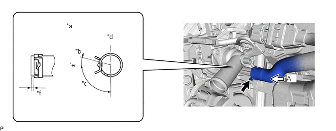
| *a | View A | *b | 15° |
| *c | 90° | *d | Upper Side |
| *e | LH Side | *f | 1 mm (0.0394 in.) or higher |
- NOTICE:
-
Make sure that the tabs of the clip are within the area shown in the illustration.
Connect the water inlet with thermostat sub-assembly connector.
16572D
2.CONNECT NO. 2 RADIATOR HOSE
Connect the No. 2 radiator hose to the water inlet with thermostat sub-assembly and slide the clip to secure it.
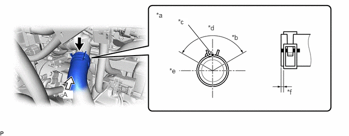
| *a | View A | *b | 120° |
| *c | Paint Mark | *d | Upper Side |
| *e | RH Side | *f | 2 to 7 mm (0.0787 to 0.276 in.) |
- NOTICE:
- ·
Align the direction of the claw on the clip with the paint mark on the hose.
·Make sure the No. 2 radiator hose is securely inserted to the stopper.
27020
3.INSTALL GENERATOR ASSEMBLY
for 100 A, 130 A Type:
Click herePower Source / Network>A25A-FKS (BATTERY / CHARGING)>GENERATOR(for 100 A, 130 A Type)>INSTALLATION
for 150 A Type:
Click herePower Source / Network>A25A-FKS (BATTERY / CHARGING)>GENERATOR(for 150 A Type)>INSTALLATION
17111
4.INSTALL INTAKE MANIFOLD
5.ADD ENGINE COOLANT
6.INSPECT FOR COOLANT LEAK