NAVIGATION / MULTI INFO DISPLAY NAVIGATION SYSTEM B15C3 Speaker Output Short
DESCRIPTION
This DTC is stored when a malfunction occurs in the speakers.
In addition, the radio and display receiver assembly detects a malfunction via the stereo component amplifier assembly.*1
| DTC No. | Detection Item | DTC Detection Condition | Trouble Area |
|---|---|---|---|
| B15C3 | Speaker Output Short | A short is detected in the speaker output circuit | ·
Harness or connector ·
Speakers ·
Stereo Component Amplifier*1 ·
Radio and Display Receiver Assembly*2 |
*1: for 9 Speakers
*2: for 6 Speakers
WIRING DIAGRAM
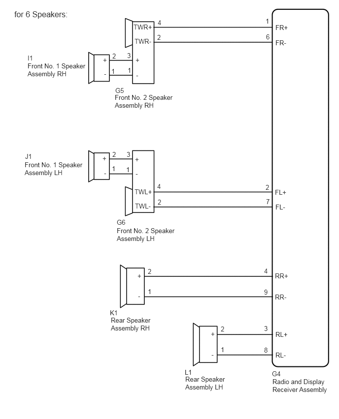
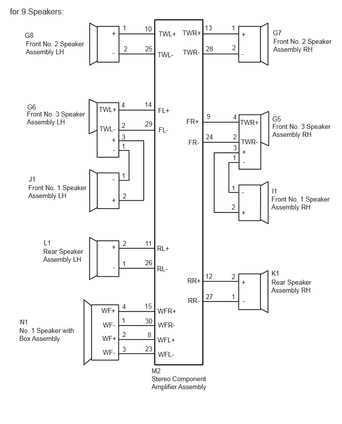
CAUTION / NOTICE / HINT
- NOTICE:
-
When replacing the radio and display receiver assembly, always replace it with a new one. If a radio and display receiver assembly which was installed to another vehicle is used, the following may occur:
- ·
A communication malfunction DTC may be stored.
·The radio and display receiver assembly may not operate normally.
- HINT:
-
Depending on the parts that are replaced during vehicle inspection or maintenance, performing initialization, registration or calibration may be needed. Refer to Precaution for Navigation System.
-
Click hereAudio / Visual / Telematics>NAVIGATION / MULTI INFO DISPLAY>NAVIGATION SYSTEM>PRECAUTION
PROCEDURE
Choose the model to be inspected.
- Result:
Result Proceed to for 6 Speakers A for 9 Speakers B
A
B
Disconnect the G4 radio and display receiver assembly connector.
Disconnect the G5 and G6 front No. 2 speaker assembly connectors.
Disconnect the K1 and L1 rear speaker assembly connectors.
Measure the resistance according to the value(s) in the table below.
- Standard Resistance:
Tester Connection Condition Specified Condition G4-1 (FR+) or G5-4 (TWR+) - Body ground Always 10 kΩ or higher G4-6 (FR-) or G5-2 (TWR-) - Body ground Always 10 kΩ or higher G4-2 (FL+) or G6-4 (TWL+) - Body ground Always 10 kΩ or higher G4-7 (FL-) or G6-2 (TWL-) - Body ground Always 10 kΩ or higher G4-4 (RR+) or K1-2 (+) - Body ground Always 10 kΩ or higher G4-9 (RR-) or K1-1 (-) - Body ground Always 10 kΩ or higher G4-3 (RL+) or L1-2 (+) - Body ground Always 10 kΩ or higher G4-8 (RL-) or L1-1 (-) - Body ground Always 10 kΩ or higher
- Result:
Proceed to OK NG
OK
NG
Disconnect the I1 and J1 front No. 1 speaker assembly connectors.
Disconnect the G5 and G6 front No. 2 speaker assembly connectors.
Measure the resistance according to the value(s) in the table below.
- Standard Resistance:
Tester Connection Condition Specified Condition I1-2 (+) or G5-3 (+) - Body ground Always 10 kΩ or higher I1-1 (-) or G5-1 (-) - Body ground Always 10 kΩ or higher J1-2 (+) or G6-3 (+) - Body ground Always 10 kΩ or higher J1-1 (-) or G6-1 (-) - Body ground Always 10 kΩ or higher
- Result:
Proceed to OK NG
OK
NG
Remove the front No. 1 speaker assembly.
Click hereAudio / Visual / Telematics>AUDIO / VIDEO>FRONT DOOR SPEAKER>REMOVAL
Inspect the front No. 1 speaker assembly.
Click hereAudio / Visual / Telematics>AUDIO / VIDEO>FRONT DOOR SPEAKER>INSPECTION
- Result:
Proceed to OK NG
OK
NG
Remove the rear speaker assembly.
Click hereAudio / Visual / Telematics>AUDIO / VIDEO>REAR DOOR SPEAKER>REMOVAL
Inspect the rear speaker assembly.
Click hereAudio / Visual / Telematics>AUDIO / VIDEO>REAR DOOR SPEAKER>INSPECTION
- Result:
Proceed to OK NG
OK
NG
Replace the front No. 2 speaker assembly with a new or known good one.
Click hereAudio / Visual / Telematics>AUDIO / VIDEO>INSTRUMENT PANEL SPEAKER>REMOVAL
Clear the DTCs.
Click hereAudio / Visual / Telematics>NAVIGATION / MULTI INFO DISPLAY>NAVIGATION SYSTEM>DTC CHECK / CLEAR
- Body Electrical > Navigation System > Clear DTCs
- 50002 212
Recheck for DTCs and check that no DTCs are output.
Click hereAudio / Visual / Telematics>NAVIGATION / MULTI INFO DISPLAY>NAVIGATION SYSTEM>DTC CHECK / CLEAR
- Body Electrical > Navigation System > Trouble Codes
- 50001 212
- OK:
No DTCs are output.
- Result:
Proceed to OK NG
OK
NG
Disconnect the M2 stereo component amplifier assembly connector.
Disconnect the G7 and G8 front No. 2 speaker assembly connector.
Disconnect the G5 and G6 front No. 3 speaker assembly connectors.
Disconnect the L1 and K1 rear speaker assembly connectors.
Disconnect the N1 rear No. 2 speaker assembly connector.
Measure the resistance according to the value(s) in the table below.
- Standard Resistance:
Tester Connection Condition Specified Condition M2-9 (FR+) or G5-4 (TWR+) - Body ground Always 10 kΩ or higher M2-24 (FR-) or G5-2 (TWR-) - Body ground Always 10 kΩ or higher M2-14 (FL+) or G6-4 (TWL+) - Body ground Always 10 kΩ or higher M2-29 (FL-) or G6-2 (TWL-) - Body ground Always 10 kΩ or higher M2-13 (TWR+) or G7-1 (+) - Body ground Always 10 kΩ or higher M2-28 (TWR-) or G7-2 (-) - Body ground Always 10 kΩ or higher M2-10 (TWL+) or G8-1 (+) - Body ground Always 10 kΩ or higher M2-25 (TWL-) or G8-2 (-) - Body ground Always 10 kΩ or higher M2-12 (RR+) or K1-2 (+) - Body ground Always 10 kΩ or higher M2-27 (RR-) or L1-1 (-) - Body ground Always 10 kΩ or higher M2-11 (RL+) or L1-2 (+) - Body ground Always 10 kΩ or higher M2-26 (RL-) or L1-1 (-) - Body ground Always 10 kΩ or higher M2-15 (WFR+) or N1-4 (WF+) - Body ground Always 10 kΩ or higher M2-30 (WFR-) or N1-1 (WF-) - Body ground Always 10 kΩ or higher M2-8 (WFL+) or N1-2 (WF+) - Body ground Always 10 kΩ or higher M2-23 (WFL-) or N1-3 (WF-) - Body ground Always 10 kΩ or higher
- Result:
Proceed to OK NG
OK
NG
Disconnect the J1 and I1 front No. 1 speaker assembly connectors.
Disconnect the G6 and G5 front No. 3 speaker assembly connectors.
Measure the resistance according to the value(s) in the table below.
- Standard Resistance:
Tester Connection Condition Specified Condition J1-2 (+) or G6-3 (+) - Body ground Always 10 kΩ or higher J1-1 (-) or G6-1 (-) - Body ground Always 10 kΩ or higher I1-2 (+) or G5-3 (+) - Body ground Always 10 kΩ or higher I1-1 (-) or G5-1 (-) - Body ground Always 10 kΩ or higher
- Result:
Proceed to OK NG
OK
NG
Remove the front No. 1 speaker assembly.
Click hereAudio / Visual / Telematics>AUDIO / VIDEO>FRONT DOOR SPEAKER>REMOVAL
Inspect the front No. 1 speaker assembly.
Click hereAudio / Visual / Telematics>AUDIO / VIDEO>FRONT DOOR SPEAKER>INSPECTION
- Result:
Proceed to OK NG
OK
NG
Remove the front No. 3 speaker assembly.
Click hereAudio / Visual / Telematics>AUDIO / VIDEO>PILLAR SPEAKER>REMOVAL
Inspect the front No. 3 speaker assembly.
Click hereAudio / Visual / Telematics>AUDIO / VIDEO>PILLAR SPEAKER>INSPECTION
- Result:
Proceed to OK NG
OK
NG
Remove the front No. 2 speaker assembly.
Click hereAudio / Visual / Telematics>AUDIO / VIDEO>INSTRUMENT PANEL SPEAKER>REMOVAL
Inspect the front No. 2 speaker assembly.
Click hereAudio / Visual / Telematics>AUDIO / VIDEO>INSTRUMENT PANEL SPEAKER>INSPECTION
- Result:
Proceed to OK NG
OK
NG
Remove the rear speaker assembly.
Click hereAudio / Visual / Telematics>AUDIO / VIDEO>REAR DOOR SPEAKER>REMOVAL
Inspect the rear speaker assembly.
Click hereAudio / Visual / Telematics>AUDIO / VIDEO>REAR DOOR SPEAKER>INSPECTION
- Result:
Proceed to OK NG
OK
NG
Remove the rear No. 2 speaker assembly.
Click hereAudio / Visual / Telematics>AUDIO / VIDEO>LUGGAGE SPEAKER>REMOVAL
Inspect the rear No. 2 speaker assembly.
Click hereAudio / Visual / Telematics>AUDIO / VIDEO>LUGGAGE SPEAKER>INSPECTION
- Result:
Proceed to OK NG
OK
NG