SEAT SEAT HEATER SYSTEM TERMINALS OF ECU
CHECK AIR CONDITIONING AMPLIFIER ASSEMBLY (for HI/MID/LO Type Front Seat Heater)
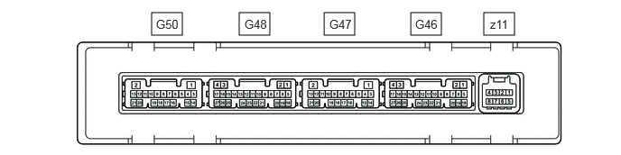
Disconnect the G46 air conditioning amplifier assembly connector.
Measure the voltage and resistance according to the value(s) in the table below.
| Terminal No. (Symbol) | Wiring Color | Terminal Description | Condition | Specified Condition |
|---|---|---|---|---|
| G46-6 (IG+) - Body ground | GR - Body ground | IG power supply | Ignition switch ON | 11 to 14 V |
| Ignition switch off | Below 1 V | |||
| G46-17 (GND) - Body ground | W-B - Body ground | Ground | Always | Below 1 Ω |
Reconnect the G46 air conditioning amplifier assembly connector.
Measure the voltage and resistance according to the value(s) in the table below.
| Terminal No. (Symbol) | Wiring Color | Terminal Description | Condition | Specified Condition |
|---|---|---|---|---|
| G48-12 (SM1R) - Body ground | LG - Body ground | RH side front seat heater drive signal | ·
Ignition switch ON ·
RH side refreshing seat switch (seat heater switch) on |
Below 1 V |
| G48-13 (SM1L) - Body ground | BE - Body ground | LH side front seat heater drive signal | ·
Ignition switch ON ·
LH side refreshing seat switch (seat heater switch) on |
Below 1 V |
| G50-3 (SG-7) - Body ground | P - Body ground*1
L - Body ground*2 |
Ground for front seat heater sensor | Always | Below 1 Ω |
| G50-12 (TSR) - Body ground | L - Body ground | RH side front seat heater sensor input signal | - | - |
| G50-13 (TSL) - Body ground | R - Body ground | LH side front seat heater sensor input signal | - | - |
*1: for LHD
*2: for RHD
Check for pulses according to the value(s) in the table below.
| Terminal No. (Symbol) | Wiring Color | Terminal Description | Condition | Specified Condition |
|---|---|---|---|---|
| G46-7 (LIN1) - Body ground | BE - Body ground | LIN communication line | Ignition switch ON | Pulse generation |
CHECK AIR CONDITIONING AMPLIFIER ASSEMBLY (w/ Rear Seat Heater)
Disconnect the G46 air conditioning amplifier assembly connector.
Measure the voltage and resistance according to the value(s) in the table below.
| Terminal No. (Symbol) | Wiring Color | Terminal Description | Condition | Specified Condition |
|---|---|---|---|---|
| G46-6 (IG+) - Body ground | GR - Body ground | IG power supply | Ignition switch ON | 11 to 14 V |
| Ignition switch off | Below 1 V | |||
| G46-17 (GND) - Body ground | W-B - Body ground | Ground | Always | Below 1 Ω |
Reconnect the G46 air conditioning amplifier assembly connector.
Measure the voltage according to the value(s) in the table below.
| Terminal No. (Symbol) | Wiring Color | Terminal Description | Condition | Specified Condition |
|---|---|---|---|---|
| G47-20 (SH2R) - Body ground | L - Body ground | RH side rear seat heater drive signal | ·
Ignition switch ON ·
Seat heater (rear) switch RH on |
Below 1 V |
| G47-21 (SH2L) - Body ground | L - Body ground | LH side rear seat heater drive signal | ·
Ignition switch ON ·
Seat heater (rear) switch LH on |
Below 1 V |
Check for pulses according to the value(s) in the table below.
| Terminal No. (Symbol) | Wiring Color | Terminal Description | Condition | Specified Condition |
|---|---|---|---|---|
| G46-7 (LIN1) - Body ground | BE - Body ground | LIN communication line | Ignition switch ON | Pulse generation |
CHECK REFRESHING SEAT SWITCH (SEAT HEATER SWITCH) (for HI/MID/LO Type Front Seat Heater)

Disconnect the G31 refreshing seat switch (seat heater switch) connector.
Measure the voltage and resistance according to the value(s) in the table below.
| Terminal No. (Symbol) | Wiring Color | Terminal Description | Condition | Specified Condition |
|---|---|---|---|---|
| G31-9 (IG) - Body ground | LA-R - Body ground | IG power supply | Ignition switch ON | 11 to 14 V |
| Ignition switch off | Below 1 V | |||
| G31-7 (E) - Body ground | LA - Body ground | Ground | Always | Below 1 Ω |
Reconnect the G31 refreshing seat switch (seat heater switch) connector.
Check for pulses according to the value(s) in the table below.
| Terminal No. (Symbol) | Wiring Color | Terminal Description | Condition | Specified Condition |
|---|---|---|---|---|
| G31-8 (SLIN) - Body ground | B - Body ground*1
W - Body ground*2 |
LIN communication line | Ignition switch ON | Pulse generation |
*1: except Manual Transaxle
*2: for Manual Transaxle
CHECK AIR CONDITIONING CONTROL ASSEMBLY (w/ Rear Seat Heater)
for Gasoline Model: Click hereVehicle Interior>HEATING / AIR CONDITIONING>AIR CONDITIONING SYSTEM (for Gasoline Model)>TERMINALS OF ECU
for HV Model: Click hereVehicle Interior>HEATING / AIR CONDITIONING>AIR CONDITIONING SYSTEM (for HV Model)>TERMINALS OF ECU