A25A-FKS FUEL FUEL PRESSURE SENSOR(for High Pressure) INSTALLATION
CAUTION / NOTICE / HINT
- NOTICE:
-
This procedure includes the installation of small-head bolts. Refer to Small-Head Bolts of Basic Repair Hint to identify the small-head bolts.
-
Click hereGeneral>INTRODUCTION>REPAIR INSTRUCTION>PRECAUTION
PROCEDURE

 89458
1.INSTALL FUEL PRESSURE SENSOR
- HINT:
-
Perform "Inspection After Repair" after replacing the fuel pressure sensor.
- ·
w/ Canister Pump Module:
Click hereEngine / Hybrid System>A25A-FKS (ENGINE CONTROL)>SFI SYSTEM (w/ Canister Pump Module)>INITIALIZATION
·w/o Canister Pump Module:
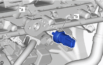
| *a | Cutout (Fuel Delivery Pipe) |
| *b | Cutout (Fuel Pressure Sensor) |
Temporarily install a new fuel pressure sensor to the fuel delivery pipe.
- NOTICE:
- ·
Make sure that the cutout of the fuel delivery pipe is aligned with the cutout of the fuel pressure sensor.
·Do not allow dust or dirt to enter the sensor.
·If a fuel pressure sensor is dropped or struck, replace it with a new one.
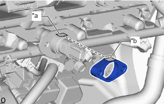
| *a | Cutout (Fuel Pressure Sensor) |
| *b | Cutout (No. 1 Fuel Pressure Sensor Holder) |
Temporarily install the No. 1 fuel pressure sensor holder to the fuel delivery pipe.
- NOTICE:
-
Make sure that the cutout of the fuel pressure sensor is aligned with the cutout of the No. 1 fuel pressure sensor holder.
Install the 2 bolts.
- Torque:
- 10 N*m (102 kgf*cm, 7 ft.*lbf)
Connect the connector to the fuel pressure sensor.
17111
2.INSTALL INTAKE MANIFOLD
3.CONNECT CABLE TO NEGATIVE BATTERY TERMINAL
- NOTICE:
-
When disconnecting the cable, some systems need to be initialized after the cable is reconnected.
-
Click hereGeneral>INTRODUCTION>REPAIR INSTRUCTION>INITIALIZATION
4.INSPECT FOR FUEL LEAK
5.PERFORM INITIALIZATION
Perform "Inspection After Repair" after replacing the fuel pressure sensor.
w/ Canister Pump Module:
Click hereEngine / Hybrid System>A25A-FKS (ENGINE CONTROL)>SFI SYSTEM (w/ Canister Pump Module)>INITIALIZATION
w/o Canister Pump Module: