EXTERIOR PANELS / TRIM FRONT BUMPER(for Off Road Package) INSTALLATION
CAUTION / NOTICE / HINT
- HINT:
- ·
A bolt without a torque specification is shown in the standard bolt chart.
Click hereGeneral>SPECIFICATIONS>STANDARD BOLT>SPECIFIED TORQUE FOR STANDARD BOLTS
PROCEDURE

 52103C
1.INSTALL FRONT BUMPER EXTENSION SUB-ASSEMBLY LH
52102F
2.INSTALL FRONT BUMPER EXTENSION SUB-ASSEMBLY RH
- HINT:
-
Use the same procedure as for the RH and LH sides.
52618
3.INSTALL FRONT BUMPER LOWER ABSORBER
51441
4.INSTALL NO. 1 ENGINE UNDER COVER
52021
5.INSTALL FRONT BUMPER REINFORCEMENT SUB-ASSEMBLY
52536
6.INSTALL FRONT BUMPER SIDE RETAINER LH
52535
7.INSTALL FRONT BUMPER SIDE RETAINER RH
- HINT:
-
Use the same procedure described for the LH side.
52614
8.INSTALL FRONT BUMPER NO. 2 ENERGY ABSORBER
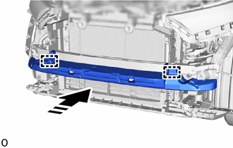

|
Install in this Direction |
Attach the guide and install the front bumper No. 2 energy absorber.
9.INSTALL FRONT BUMPER ASSEMBLY
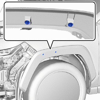
Install 2 new clips to the front fender moulding sub-assembly LH.
- NOTICE:
-
If the front bumper assembly has been removed, replace the clip with a new one.
- HINT:
-
Use the same procedure as for the RH and LH sides.
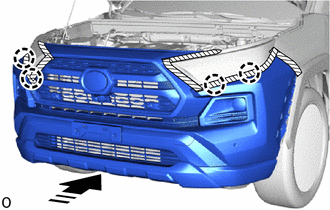
|
|
Install in this Direction |
Attach the claw to temporarily install the front bumper assembly.
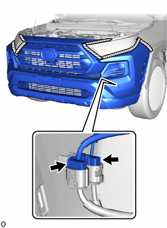
Connect the 2 connectors.
Install the front bumper assembly to the front bumper side retainer LH.
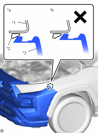
| *a | Correct |
| *b | Incorrect |
| *1 | Front Fender Panel |
| *2 | Front Bumper Side Retainer LH |
| *3 | Front Bumper Assembly |
Make sure that the front bumper assembly claw contacts the front bumper side retainer LH as shown in the illustration.
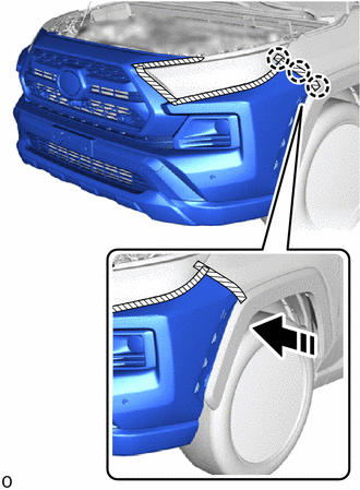
|
|
Install in this Direction |
Attach the claw to install the front bumper assembly as shown in the illustration.
- HINT:
-
Use the same procedure as for the RH and LH sides.
After installation, if there is a clearance and the front bumper assembly claw can be seen as shown in the illustration, the installation condition is incorrect. Perform the procedure from step 1 again.
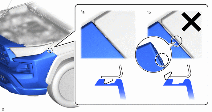
| *a | Correct | *b | Incorrect |
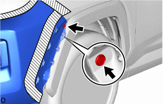
Install the 2 clips.
- HINT:
-
Use the same procedure as for the RH and LH sides.
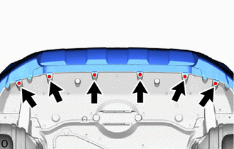
Install the 6 screws.
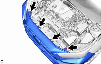
Install the 4 bolts.
Remove the protective tape.
75602A
10.INSTALL FRONT FENDER MOULDING SUB-ASSEMBLY LH
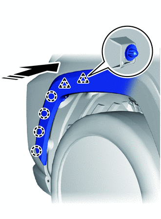
|
|
Install in this Direction |
Attach the clip and claw to install the front fender moulding sub-assembly LH.
Remove the protective tape.
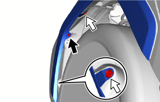

|
Screw |

|
Clip |
Install the screw.
Install the 2 clips.
75601A
11.INSTALL FRONT FENDER MOULDING SUB-ASSEMBLY RH
- HINT:
-
Use the same procedure as for the LH side.
53896B
12.INSTALL FRONT FENDER FRONT SPLASH SHIELD LH
- HINT:
-
Use the same procedure described for the RH side.
-
Click hereVehicle Exterior>WIPER / WASHER>WASHER MOTOR>INSTALLATION
53895B
13.INSTALL FRONT FENDER FRONT SPLASH SHIELD RH
- HINT:
-
Use the same procedure as for the LH side.
14.ADJUST FOG LIGHT ASSEMBLY
86790
15.ADJUST FRONT TELEVISION CAMERA ASSEMBLY (w/ Panoramic View Monitor System)