GF1A TRANSFER / 4WD / AWD DYNAMIC TORQUE CONTROL 4WD/AWD SYSTEM 4WD Control Switch Circuit
WIRING DIAGRAM
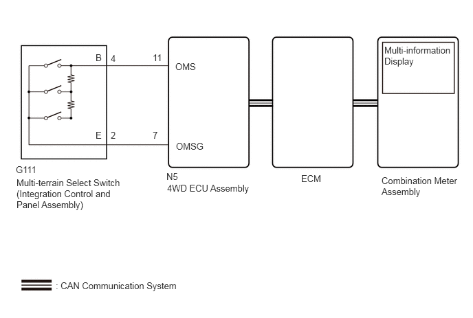
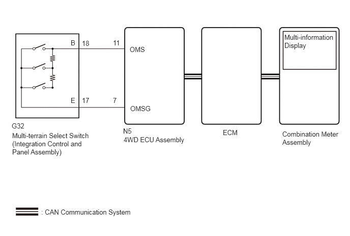
PROCEDURE
Turn the ignition switch off.
Connect the GTS the DLC3.
Turn the ignition switch to ON.
Turn the GTS on.
Enter the following menus: Powertrain / Engine / Data List.
According to the display on the GTS, read the Data List.
- Powertrain > Engine > Data List
-
Tester Display Measurement Item Range Normal Condition Diagnostic Note Off-road Guidance Status Off road mode status Normal, Grass & Snow, Mud & Sand, Loose Rock, Mogul or Rock & Dirt - -
- Powertrain > Engine > Data List
-
Tester Display Off-road Guidance Status - 50003 372 1098
Operate the multi-terrain select switch (integration control and panel assembly) and check that the Data List display and multi-information display message change according to switch operation.
- OK:
Multi-terrain Select Switch (Integration Control and Panel Assembly) Operation Data List Display Multi-information Display Message NORMAL Normal NORMAL MUD&SAND Mud & Sand MUD&SAND ROCK&DIRT Rock & Dirt ROCK&DIRT
- Result:
Result Proceed to When the switch is operated, the Data List display and message do not change A When the switch is operated, the Data List display changes, but message do not change B When the switch is operated, the Data List display and message change normally C
A
B
Click hereVehicle Interior>METER / GAUGE / DISPLAY>METER / GAUGE SYSTEM>HOW TO PROCEED WITH TROUBLESHOOTING
C
Click hereGeneral>INTRODUCTION>HOW TO TROUBLESHOOT ECU CONTROLLED SYSTEMS>HOW TO PROCEED WITH TROUBLESHOOTING
Check the vehicle specification.
- Result:
Result Proceed to for Manual Transaxle A except Manual Transaxle B
A
B
Inspect the multi-terrain select switch (integration control and panel assembly).
Click hereDrivetrain>GF1A (TRANSFER / 4WD / AWD)>MULTI-TERRAIN SELECT SWITCH>INSPECTION
- Result:
Proceed to OK NG
OK
NG
Turn the ignition switch off.
Disconnect the N5 4WD ECU assembly connector.
Disconnect the G111 multi-terrain select switch (integration control and panel assembly) connector.
Measure the resistance according to the value(s) in the table below.
- Standard Resistance:
Tester Connection Condition Specified Condition N5-11 (OMS) - G111-4 (B) Always Below 1 Ω N5-7 (OMSG) - G111-2 (E) Always Below 1 Ω N5-11 (OMS) or G111-4 (B) - Body ground Always 10 kΩ or higher N5-7 (OMSG) or G111-2 (E) - Body ground Always 10 kΩ or higher N5-11 (OMS) or G111-4 (B) - N5-7 (OMSG) or G111-2 (E) Always 10 kΩ or higher
- Result:
Proceed to OK NG
OK
NG
Inspect the multi-terrain select switch (integration control and panel assembly).
Click hereDrivetrain>GF1A (TRANSFER / 4WD / AWD)>MULTI-TERRAIN SELECT SWITCH>INSPECTION
- Result:
Proceed to OK NG
OK
NG
Turn the ignition switch off.
Disconnect the N5 4WD ECU assembly connector.
Disconnect the G32 multi-terrain select switch (integration control and panel assembly) connector.
Measure the resistance according to the value(s) in the table below.
- Standard Resistance:
Tester Connection Condition Specified Condition N5-11 (OMS) - G32-18 (B) Always Below 1 Ω N5-7 (OMSG) - G32-17 (E) Always Below 1 Ω N5-11 (OMS) or G32-18 (B) - Body ground Always 10 kΩ or higher N5-7 (OMSG) or G32-17 (E) - Body ground Always 10 kΩ or higher N5-11 (OMS) or G32-18 (B) - N5-7 (OMSG) or G32-17 (E) Always 10 kΩ or higher
- Result:
Proceed to OK NG
OK
NG