TELEMATICS TELEMATICS TRANSCEIVER INSTALLATION
CAUTION / NOTICE / HINT
- HINT:
- ·
Use the same procedure for RHD and LHD vehicles.
·The procedure listed below is for LHD vehicles.
PROCEDURE

 86740
1.INSTALL TELEPHONE TRANSCEIVER ASSEMBLY
86457A
2.INSTALL NO. 2 MULTI-MEDIA MODULE BRACKET
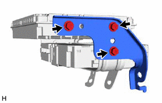
w/ Navigation System:
Install the No. 2 multi-media module bracket with the 3 screws.
- Torque:
- 3.0 N*m (31 kgf*cm, 27 in.*lbf)
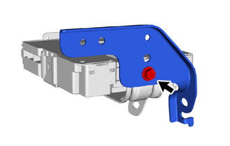
w/o Navigation System:
Install the No. 2 multi-media module bracket with the screw.
- Torque:
- 3.0 N*m (31 kgf*cm, 27 in.*lbf)
86457
3.INSTALL NO. 1 MULTI-MEDIA MODULE BRACKET
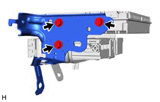
w/ Navigation System:
Install the No. 1 multi-media module bracket with the 3 screws.
- Torque:
- 3.0 N*m (31 kgf*cm, 27 in.*lbf)
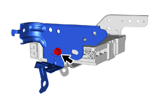
w/o Navigation System:
Install the No. 1 multi-media module bracket with the screw.
- Torque:
- 3.0 N*m (31 kgf*cm, 27 in.*lbf)
86842J
4.INSTALL NO. 2 NAVIGATION WIRE (w/ Connector Holder)
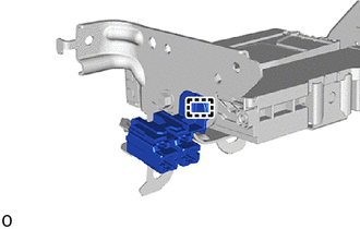
Attach the clamp to install the No. 2 navigation wire.
86842J
5.INSTALL NO. 2 NAVIGATION WIRE (for LHD)
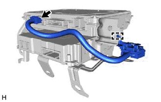
w/ Navigation System, for eCall:
Attach the clamp to install the No. 2 navigation wire.
Connect the connector.
w/ Navigation System, for ERA-GLONASS:
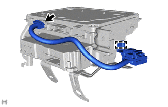
Attach the clamp to install the No. 2 navigation wire.
Connect the connector.
86842J
6.INSTALL NO. 2 NAVIGATION WIRE (for RHD)
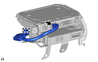
Attach the clamp to install the No. 2 navigation wire.
Connect the connector.
86101J
7.INSTALL NO. 2 ANTENNA CORD SUB-ASSEMBLY (for LHD)
w/ Navigation System, for eCall:
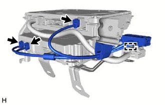
Attach the clamp to install the No. 2 antenna cord sub-assembly.
Connect the 3 connectors.
w/ Navigation System, for ERA-GLONASS:
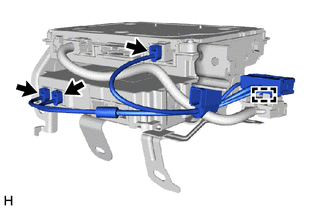
Attach the clamp to install the No. 2 antenna cord sub-assembly.
Connect the 3 connectors.
w/ Navigation System, for ERA-GLONASS:
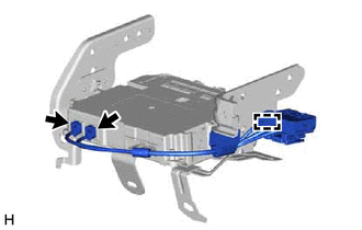
Attach the clamp to install the No. 2 antenna cord sub-assembly.
Connect the 2 connectors.
86101J
8.INSTALL NO. 2 ANTENNA CORD SUB-ASSEMBLY (for RHD)
w/ Navigation System:
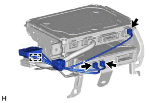
Attach the clamp to install the No. 2 antenna cord sub-assembly.
Connect the 3 connectors.
w/o Navigation System:
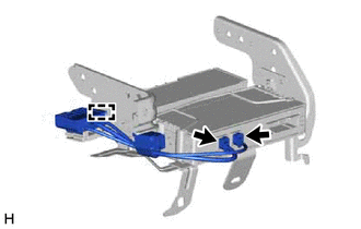
Attach the clamp to install the No. 2 antenna cord sub-assembly.
Connect the 2 connectors.
9.INSTALL TELEPHONE TRANSCEIVER ASSEMBLY WITH BRACKET (for LHD)
w/ Navigation System, for eCall:
Connect each connector.
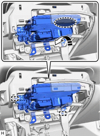

|
Place Hand Here |

|
Install in this Direction |
Place your hand at the position shown in the illustration, and then while bending the instrument panel safety pad assembly, attach the guide and temporarily install the telephone transceiver assembly with bracket.
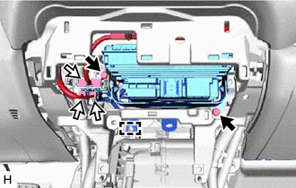

|
Bolt |

|
Connector |
Attach the clamp and connect the 3 connectors.
Install the 2 bolts.
- Torque:
- 12 N*m (122 kgf*cm, 9 ft.*lbf)
w/ Navigation System, for ERA-GLONASS:
Connect each connector.
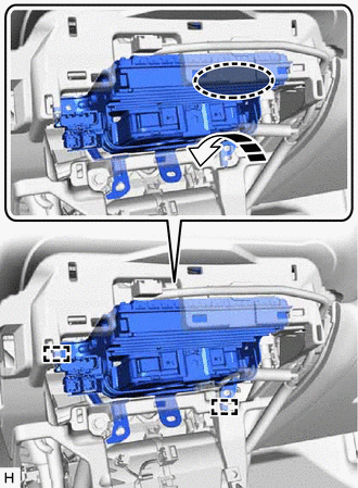
|
|
Place Hand Here |
|
|
Install in this Direction |
Place your hand at the position shown in the illustration, and then while bending the instrument panel safety pad assembly, attach the guide and temporarily install the telephone transceiver assembly with bracket.
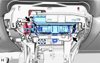
Attach the clamp and connect the 3 connectors.
Install the 2 bolts.
- Torque:
- 12 N*m (122 kgf*cm, 9 ft.*lbf)
w/o Navigation System, for ERA-GLONASS:
Connect the connector.
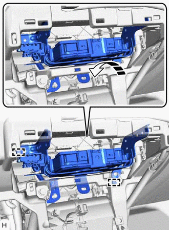
|
|
Install in this Direction |
Attach the guide to temporarily install the telephone transceiver assembly with bracket.
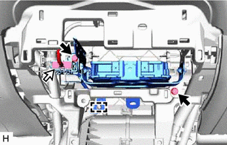
|
|
Bolt |
|
|
Connector |
Attach the clamp and connect the connector.
Install the 2 bolts.
- Torque:
- 12 N*m (122 kgf*cm, 9 ft.*lbf)
w/ Connector Holder:
Connect the connector.
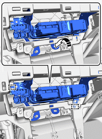
|
|
Install in this Direction |
Attach the guide to temporarily install the telephone transceiver assembly with bracket.
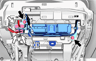
|
|
Bolt |
|
|
Connector |
Attach the clamp and connect the 3 connectors.
Install the 2 bolts.
- Torque:
- 12 N*m (122 kgf*cm, 9 ft.*lbf)
10.INSTALL TELEPHONE TRANSCEIVER ASSEMBLY WITH BRACKET (for RHD)
w/ Navigation System:
Connect each connector.
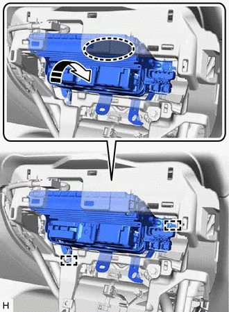
|
|
Place Hand Here |
|
|
Install in this Direction |
Place your hand at the position shown in the illustration, and then while bending the instrument panel safety pad assembly, attach the guide and temporarily install the telephone transceiver assembly with bracket.
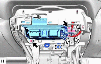
|
|
Bolt |
|
|
Connector |
Attach the clamp and connect the 3 connectors.
Install the 2 bolts.
- Torque:
- 12 N*m (122 kgf*cm, 9 ft.*lbf)
w/o Navigation System:
Connect the connector.
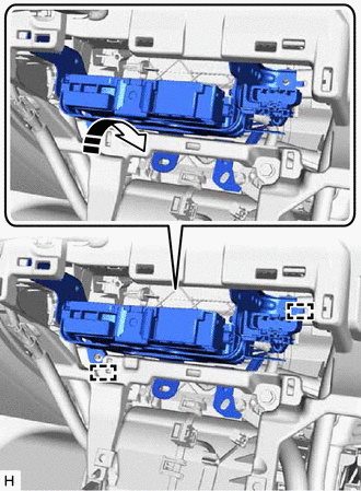
|
|
Install in this Direction |
Attach the guide to temporarily install the telephone transceiver assembly with bracket.
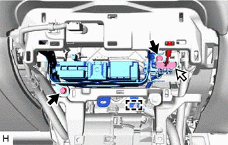
|
|
Bolt |
|
|
Connector |
Attach the clamp and connect the connector.
Install the 2 bolts.
- Torque:
- 12 N*m (122 kgf*cm, 9 ft.*lbf)
w/ Connector Holder:
Connect the connector.
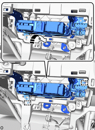
|
|
Install in this Direction |
Attach the guide to temporarily install the telephone transceiver assembly with bracket.
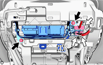
|
|
Bolt |
|
|
Connector |
Attach the clamp and connect the 3 connectors.
Install the 2 bolts.
- Torque:
- 12 N*m (122 kgf*cm, 9 ft.*lbf)
55434B
11.INSTALL LOWER CENTER INSTRUMENT PANEL FINISH PANEL
55900
12.INSTALL AIR CONDITIONING CONTROL ASSEMBLY
13.INSTALL CONSOLE BOX ASSEMBLY
14.PERFORM REGISTRATION
for eCall:
Click hereAudio / Visual / Telematics>TELEMATICS>TELEMATICS SYSTEM (for eCall)>REGISTRATION
for ERA-GLONASS:
Click hereAudio / Visual / Telematics>TELEMATICS>TELEMATICS SYSTEM (for ERA-GLONASS)>REGISTRATION