PARKING BRAKE ELECTRIC PARKING BRAKE SYSTEM(w/o Vacuum Brake Booster) Electric Parking Brake System AUTO Function Circuit
DESCRIPTION
The parking brake ECU assembly receives shift position information from the hybrid vehicle control ECU assembly via CAN communication. Also, the parking brake ECU assembly receives wheel speed information and stop light switch information from the skid control ECU (brake booster with master cylinder assembly).
The electric parking brake system AUTO control (shift-linked) function automatically releases the parking brake when the following conditions are met: 1) power switch on (IG), 2) brake pedal depressed, and 3) shift lever moved out of P. Also, when the shift lever is moved to P with the vehicle in this condition, the function automatically locks the parking brake.
WIRING DIAGRAM
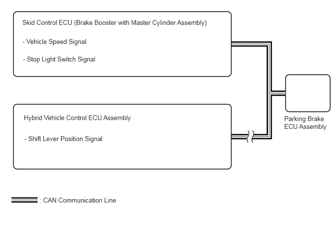
CAUTION / NOTICE / HINT
- NOTICE:
- ·
The electric parking brake may still operate up to 20 seconds after the power switch is turned off. Before disconnecting connectors or fuses, turn the power switch off and wait 20 seconds or more.
·When replacing the parking brake ECU assembly, operate the electric parking brake switch (integration control and panel assembly) from the lock side to the release side, as the parking brake indicator light blinks when the power switch is first turned on (IG).
PROCEDURE
Check the electronically controlled brake system (w/o Vacuum Brake Booster) DTCs and check if speed sensor system or stop light switch system DTCs are stored.
- Chassis > ABS/VSC/TRC > Trouble Codes
- 50001 105
- Result:
Result Proceed to DTC is not output A DTC is output B
A
B
Check the DTCs.
- Powertrain > Hybrid Control > Trouble Codes
- 50001 397
- Result:
Result Proceed to DTC is not output A DTC is output B
A
B
for 2WD: Click hereEngine / Hybrid System>HYBRID / BATTERY CONTROL>HYBRID CONTROL SYSTEM (for 2WD with NICKEL METAL HYDRIDE BATTERY)>HOW TO PROCEED WITH TROUBLESHOOTING
for 4WD/AWD: Click hereEngine / Hybrid System>HYBRID / BATTERY CONTROL>HYBRID CONTROL SYSTEM (for 4WD/AWD with NICKEL METAL HYDRIDE BATTERY)>HOW TO PROCEED WITH TROUBLESHOOTING