A25A-FKS FUEL FUEL INJECTOR(for Port Injection) INSTALLATION
CAUTION / NOTICE / HINT
- NOTICE:
-
This procedure includes the installation of small-head bolts. Refer to Small-Head Bolts of Basic Repair Hint to identify the small-head bolts.
-
Click hereGeneral>INTRODUCTION>REPAIR INSTRUCTION>PRECAUTION
PROCEDURE

 23250F
1.INSTALL PORT FUEL INJECTOR ASSEMBLY
- HINT:
-
Perform "Inspection After Repair" after replacing a port fuel injector assembly.
- ·
w/ Canister Pump Module:
Click hereEngine / Hybrid System>A25A-FKS (ENGINE CONTROL)>SFI SYSTEM (w/ Canister Pump Module)>INITIALIZATION
·w/o Canister Pump Module:
Apply a light coat of spindle oil or gasoline to 4 new O-rings, and install 1 to each port fuel injector assembly.
- NOTICE:
-
Check that there is no damage or foreign matter on the groove of the port fuel injector assembly when installing the O-ring to each port fuel injector assembly.
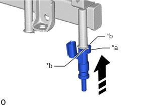
| *a | Stopper |
| *b | Claw |
Install the 4 port fuel injector assemblies to the fuel delivery pipe sub-assembly.
- NOTICE:
- ·
Make sure that the port fuel injector assembly is located within the stopper as shown in the illustration.
·Check that the port fuel injector assembly installation holes of the fuel delivery pipe sub-assembly are not damaged and are free of foreign matter.
·Make sure that the O-ring is not damaged, twisted or moved out of place when installing the port fuel injector assembly.
82125N
2.INSTALL NO. 5 ENGINE WIRE
Attach the 2 clamps and install the No. 5 engine wire to the fuel delivery pipe sub-assembly.
Connect the 5 connectors to the 4 port fuel injector assemblies and fuel pressure sensor.
23291
3.INSTALL INJECTOR VIBRATION INSULATOR
Install 4 new injector vibration insulators to the cylinder head sub-assembly.
23807V
4.INSTALL NO. 1 DELIVERY PIPE SPACER
Install the 2 No. 1 delivery pipe spacers to the cylinder head sub-assembly.
23807
5.INSTALL FUEL DELIVERY PIPE SUB-ASSEMBLY
Place the fuel delivery pipe sub-assembly to the cylinder head sub-assembly.
- NOTICE:
-
Be careful not to drop the port fuel injector assemblies when installing the fuel delivery pipe sub-assembly.
Install the fuel delivery pipe sub-assembly with the 2 bolts.
- Torque:
- 28.5 N*m (291 kgf*cm, 21 ft.*lbf)
Connect the connector to the No. 5 engine wire.
23901
6.CONNECT FUEL TUBE SUB-ASSEMBLY
Connect the fuel tube sub-assembly to the fuel delivery pipe sub-assembly.
Click hereEngine / Hybrid System>A25A-FKS (FUEL)>FUEL SYSTEM>PRECAUTION
Install the fuel pipe clamp to the fuel tube connector.
23801P
7.TEMPORARILY INSTALL NO. 1 FUEL PIPE SUB-ASSEMBLY
23100X
8.INSTALL FUEL PUMP ASSEMBLY
23801P
9.INSTALL NO. 1 FUEL PIPE SUB-ASSEMBLY
17111
10.INSTALL INTAKE MANIFOLD
11.CONNECT CABLE TO NEGATIVE BATTERY TERMINAL
- NOTICE:
-
When disconnecting the cable, some systems need to be initialized after the cable is reconnected.
-
Click hereGeneral>INTRODUCTION>REPAIR INSTRUCTION>INITIALIZATION
12.INSPECT FOR FUEL LEAK
13.PERFORM INITIALIZATION
Perform "Inspection After Repair" after replacing a port fuel injector assembly.
w/ Canister Pump Module:
Click hereEngine / Hybrid System>A25A-FKS (ENGINE CONTROL)>SFI SYSTEM (w/ Canister Pump Module)>INITIALIZATION
w/o Canister Pump Module: