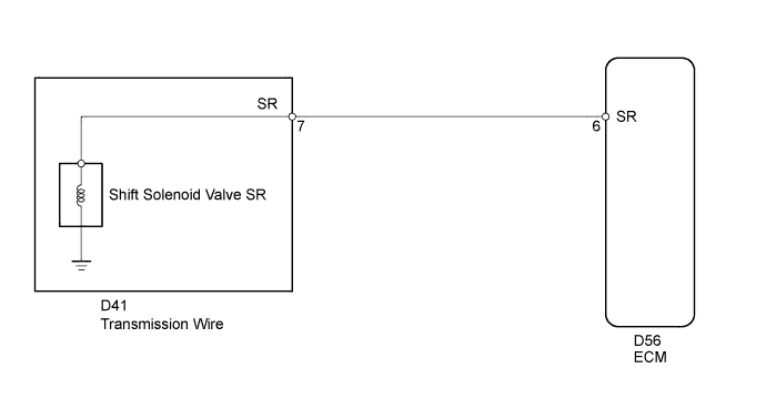
DTC P0985 Shift Solenoid "E" Control Circuit Low (Shift Solenoid Valve SR) |
DTC P0986 Shift Solenoid "E" Control Circuit High (Shift Solenoid Valve SR) |
| DTC Code | DTC Detection Condition | Trouble Area |
| P0985 | ECM detects short in solenoid valve SR circuit 2 times when solenoid valve SR is operated (1-trip detection logic) |
|
| P0986 | ECM detects open in solenoid valve SR circuit 2 times when solenoid valve SR is not operated (1-trip detection logic) |
|
| Related DTCs | P0985: Shift solenoid valve SR/Range check (Low resistance) P0986: Shift solenoid valve SR/Range check (High resistance) |
| Required sensors/Components | Shift solenoid valve SR |
| Frequency of operation | Continuous |
| Duration | 0.128 seconds or more |
| MIL operation | Immediately |
| Sequence of operation | None |
| The monitor will run whenever the following DTCs are not present | None |
| Battery voltage | 8 V or more |
| Ignition switch | ON |
| Starter | OFF |
| Shift solenoid valve SR | ON |
| Shift solenoid valve SR | OFF |
| Shift solenoid valve SR resistance | 8 Ω or less |
| Shift solenoid valve SR resistance | 100 kΩ or more |
| Shift solenoid valve SR resistance | 11 to 15 Ω at 20°C (68°F) |
| ECM gear shift command | 1st | 2nd | 3rd | 4th | 5th |
| Shift solenoid valve SR | OFF | OFF | OFF | OFF | ON |
| 1.INSPECT TRANSMISSION WIRE (SHIFT SOLENOID VALVE SR) |
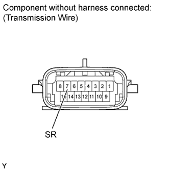 |
Disconnect the D41 transmission wire connector.
Measure the resistance according to the value(s) in the table below.
| Tester Connection | Condition | Specified Condition |
| 7 (SR) - Body ground | 20°C (68°F) | 11 to 15 Ω |
|
| ||||
| OK | |
 |
| 2.CHECK HARNESS AND CONNECTOR (TRANSMISSION WIRE - ECM) |
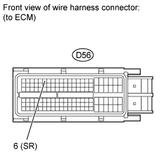 |
Disconnect the D56 ECM connector.
Measure the resistance according to the value(s) in the table below.
| Tester Connection | Condition | Specified Condition |
| D56-6 (SR) - Body ground | 20°C (68°F) | 11 to 15 Ω |
|
| ||||
| OK | ||
 | ||
| ||
| 3.INSPECT SHIFT SOLENOID VALVE SR |
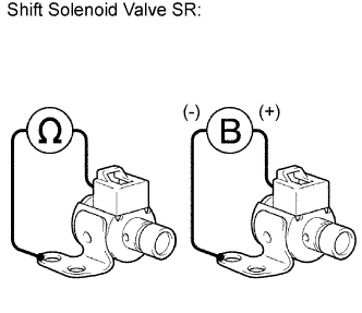 |
Remove the shift solenoid valve SR.
Measure the resistance according to the value(s) in the table below.
| Tester Connection | Condition | Specified Condition |
| Shift solenoid valve SR connector terminal - Shift solenoid valve SR body | 20°C (68°F) | 11 to 15 Ω |
Connect the battery positive (+) lead to the terminal of the solenoid valve connector, and the negative (-) lead to the solenoid valve body. Then check that the valve moves and makes an operating noise.
|
| ||||
| OK | ||
| ||
| ||

