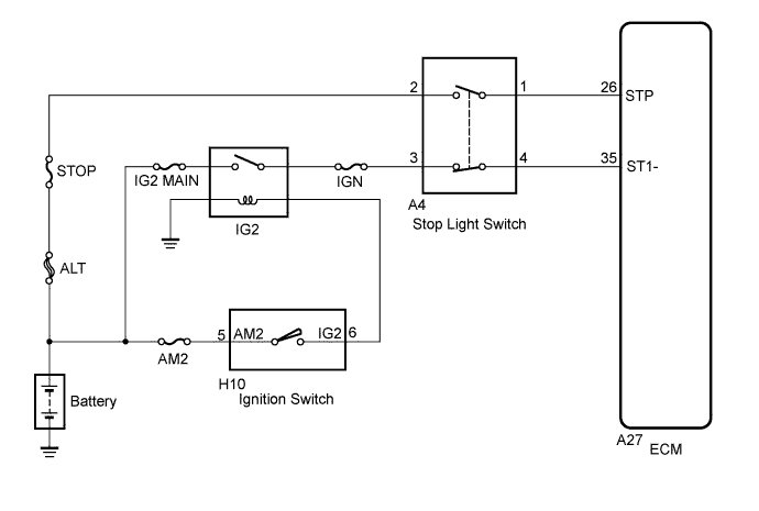
DTC P0571 Brake Switch "A" Circuit |
| DTC No. | DTC Detection Condition | Trouble Area |
| P0571 | Voltage of STP terminal and that of ST1- terminal of ECM are less than 1 V for 0.5 seconds. or more. |
|
| This trouble code is output when the BRK relay error signal from the skid control ECU for 0.2 seconds. or more while the dynamic cruise control is in operation. | VSC system |
| 1.CHECK FOR DTC (IN VEHICLE STABILITY CONTROL SYSTEM) |
Check for DTCs in Vehicle Stability Control System (Click here).
|
| ||||
| OK | |
 |
| 2.READ VALUE USING TECHSTREAM (STOP LIGHT SWITCH) |
Connect the Techstream to the DLC3.
Turn the ignition switch to ON.
Turn the Techstream on.
Enter the following menus: Powertrain / Cruise Control / Data List.
Check the Data List for proper functioning of the cruise control main switch.
| Tester Display | Measurement Item/Range | Normal Condition | Diagnostic Note |
| Stop Light SW M-CPU | Stop light switch signal (Main CPU) / ON or OFF | ON: Brake pedal depressed OFF: Brake pedal released | - |
| Result | Proceed to |
| NG | A |
| OK (for 2UZ-FE) | B |
| OK (for 3UR-FE) | C |
| OK (for 3UR-FBE) | D |
|
| ||||
|
| ||||
|
| ||||
| A | |
|
| 3.CHECK HARNESS AND CONNECTOR (STOP LIGHT SWITCH - BATTERY) |
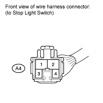 |
Disconnect the A4 connector from the stop light switch.
Measure the voltage according to the value(s) in the table below.
| Tester Connection | Switch Condition | Specified Condition |
| A4-2 - Body ground | Always | 11 to 14 V |
| A4-3 - Body ground | Ignition switch ON | 11 to 14 V |
Reconnect the stop light switch connector.
|
| ||||
| OK | |
|
| 4.INSPECT STOP LIGHT SWITCH |
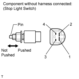 |
Remove the stop light switch (Click here).
Measure the resistance according to the value(s) in the table below.
| Tester Connection | Switch Condition | Specified Condition |
| 1 - 2 | Switch pin not pushed | Below 1 Ω |
| 3 - 4 | Switch pin not pushed | 10 kΩ or higher |
| 1 - 2 | Switch pin pushed | 10 kΩ or higher |
| 3 - 4 | Switch pin pushed | Below 1 Ω |
Reinstall the stop light switch.
|
| ||||
| OK | |
|
| 5.CHECK ECM |
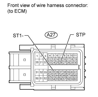 |
Disconnect the A27 connector from the ECM.
Turn the ignition switch to ON.
Measure the voltage according to the value(s) in the table below.
| Tester Connection | Condition | Specified Condition |
| A27-26 (STP) - Body ground | Brake pedal is depressed | 11 to 14 V |
| A27-26 (STP) - Body ground | Brake pedal is released | Below 1 V |
| A27-35 (ST1-) - Body ground | Brake pedal is depressed | Below 1 V |
| A27-35 (ST1-) - Body ground | Brake pedal is released | 11 to 14 V |
| Result | Proceed to |
| NG | A |
| OK (for 2UZ-FE) | B |
| OK (for 3UR-FE) | C |
| OK (for 3UR-FBE) | D |
Reconnect the ECM connector.
|
| ||||
|
| ||||
|
| ||||
| A | ||
 | ||
| ||
