| B |  |
| GO TO AIR PUMP INSPECTION PROCEDURE |
| C | |
| GO TO DTC CHART (Click here) |
DTC P2444 Secondary Air Injection System Pump Stuck On Bank1 |
DTC P2445 Secondary Air Injection System Pump Stuck Off Bank1 |
DTC P2446 Secondary Air Injection System Pump Stuck On Bank 2 |
DTC P2447 Secondary Air Injection System Pump Stuck Off Bank 2 |
| DTC No. | DTC Detection Condition | Trouble Area |
| P2444 P2446 | Secondary air pressure more than 2.4 kPa (18 mmHg) despite ECM commanding air pump to turn off (2 trip detection logic) |
|
| P2445 P2447 | Secondary air pressure less than 2.4 kPa (18 mmHg) despite ECM commanding air pump to turn on (2 trip detection logic) |
|
| Related DTCs | P2444: Air pump stuck ON P2445: Air pump stuck OFF P2446: Air pump stuck ON P2447: Air pump stuck OFF |
| Required Sensors/Components (Main) | Pressure sensor |
| Required Sensors/Components (Related) | - |
| Frequency of Operation | Once per drive cycle |
| Duration | Case 3: 1.5 seconds Case 1, 2: 7 seconds |
| MIL Operation | 2 driving cycles |
| Sequence of Operation | None |
| Monitor runs whenever following DTCs not present | P0010, P0020 (VVT Oil control valve) P0011, P0021 (VVT System - Advance) P0012, P0022 (VVT System - Retard) P0013, P0023 (Exhaust VVT Oil Control Valve) P0014, P0024 (Exhaust VVT System - Advance) P0015, P0025 (Exhaust VVT System - Retard) P0016, P0018 (VVT System - Misalignment) P0017, P0019 (Exhaust VVT System - Misalignment) P0031, P0032, P0051, P0052 (Air fuel ratio Sensor Heater) P0102, P0103 (Mass air flow meter) P0112, P0113 (Intake air temperature sensor) P0115, P0117, P0118 (Engine coolant temperature sensor) P0120, P0121, P0122, P0123, P0220, P0222, P0223, P2135 (Throttle position sensor) P0125 (Insufficient coolant temperature for closed loop fuel control) P0171, P0172, P0174, P0175 (Fuel system) P0301 - P0308 (Misfire) P0327, P0328, P0332, P0333, P032C, P032D, P033C, P033D (Knock sensor) P0335 (Crankshaft position sensor) P0340, P0342, P0343, P0345, P0347, P0348, P1340 (VVT sensor) P0351 - P0358 (Igniter) P0365, P0367, P0368, P0390, P0392, P0393 (Exhaust VVT sensor) P0451, P0452, P0453, P1451, P1452 P1453, P1455 (EVAP system) P0500 (Vehicle speed sensor) P2195, P2196, P2197, P2198, P2237, P2238, P2239, P2240, P2241, P2242, P2252, P2253, P2255, P2256, P2A00, P2A03 (Front oxygen/Air fuel ratio sensor) P2431 - P2438 (Secondary air injection system pressure sensor) |
| Battery voltage | 11 V or more |
| Atmospheric pressure | 45 kPa (337.5 mmHg) or more |
| Secondary air injection pump | ON |
| Secondary air injection switching valve | ON |
| Engine speed | Less than 3750 rpm |
| Secondary air injection pump | OFF |
| Engine speed | Less than 3750 rpm |
| Secondary air injection system monitor during secondary air injection ON | Completed |
| Coolant temperature at engine start | Less than 5°C (41°F) |
| Ambient temperature at engine start | -15°C (5°F) or more |
| Cumulative intake air amount | 100 g/sec. or more |
| Secondary air injection system monitor during secondary air injection ON | Completed |
| Engine speed | 3000 rpm or more |
| Throttle angle | 20° or more |
| AIR valve | OFF |
| Duration of the following condition | 5 to 60 minutes |
| Engine coolant temperature | 25°C (77°F) or more |
| AIR pressure during AIR ON | 2.4 kPa or more and pulse is generated |
| AIR pressure during AIR ON | Less than 2.4 kPa and pulse is generated |
| AIR pressure during AIR ON | 2.4 kPa or more and pulse is not generated |
| AIR pressure during AIR ON | Less than 2.4 kPa and pulse is not generated |
| AIR pressure during AIR OFF | 2.4 kPa or more and pulse is generated |
| AIR pressure during AIR OFF | Less than 2.4 kPa and pulse is generated |
| AIR pressure during AIR OFF | 2.4 kPa or more and pulse is not generated |
| AIR pressure during AIR OFF | Less than 2.4 kPa and pulse is not generated |
| Both of following conditions met: | (a) and (b) |
| (a) Not condition 6 | Met |
| (b) Not condition 8 | Met |
| Both of following conditions met: | (a) and (b) |
| (a) Not condition 1 | Met |
| (b) Not condition 3 | Met |
| AIR amount | 140 L/min or less |
| Air Pump | ON |
| Air Switching Valve | Open |
| Pressure | 2.4 kPa or more |
| Pulsation Detection | Exhaust gas pulsation detected |
| Air Pump | OFF |
| Air Switching Valve | Open |
| Pressure | Less than 2.4 kPa |
| Pulsation Detection | Exhaust gas pulsation detected |
| Air Pump | ON |
| Air Switching Valve | Closed |
| Pressure | 2.4 kPa or more |
| Pulsation Detection | Exhaust gas pulsation not detected |
| Air Pump | OFF |
| Air Switching Valve | Close |
| Pressure | Less than 2.4 kPa |
| Pulsation Detection | Exhaust gas pulsation not detected |
| Air Pump | ON |
| Air Switching Valve | Open |
| Pressure | 2.4 kPa or more |
| Pulsation Detection | Exhaust gas pulsation detected |
| Air Pump | OFF |
| Air Switching Valve | Open |
| Pressure | Less than 2.4 kPa |
| Pulsation Detection | Exhaust gas pulsation detected |
| Air Pump | ON |
| Air Switching Valve | Closed |
| Pressure | 2.4 kPa or more |
| Pulsation Detection | Exhaust gas pulsation not detected |
| Air Pump | OFF |
| Air Switching Valve | Close |
| Pressure | Less than 2.4 kPa |
| Pulsation Detection | Exhaust gas pulsation not detected |
| Detected Condition while AIR Operating: Air Pump ON, ASV Open | Detected Condition while AIR not Operating: Air Pump OFF, ASV Closed | ECM Determination | DTC Output |
| Case 1 | Case 8 | Normal | - |
| Case 1 | Case 6 | ASV stuck open | P2440 or P2442 |
| Case 1 | Case 7 | Air pump stuck ON | P2444 or P2446 |
| Case 2 | Case 8 | Air pump stuck OFF | P2445 or P2447 |
| Case 3 | Case 8 | ASV stuck closed | P2441 or P2443 |
| Case 1 | Case 5 | ASV stuck open and air pump stuck ON | P2440 and P2444 or P2442 and P2446 |
| Case 2 | Case 6 | ASV stuck open and air pump stuck OFF | P2440 and P2445 or P2442 and P2447 |
| Case 3 | Case 7 | ASV stuck closed and air pump stuck ON | P2441 and P2444 or P2443 and P2446 |
| Case 4 | Case 8 | ASV stuck closed and air pump stuck OFF | P2441 and P2445 or P2443 and P2447 |
| Tester Operation | Air Pump | ASV | Pressure*1 | Pulsation*2 |
| AIR PUMP: ON, ASV: OPEN | ON | OPEN | 2.4 kPa or more | 20 kPa or more |
| AIR PUMP: OFF, ASV: CLOSE | OFF | CLOSE | Less than 2.4 kPa | Less than 30 kPa |
| 1.CHECK ANY OTHER DTCS OUTPUT (IN ADDITION TO DTC P2444, P2445, P2446 AND/OR P2447) |
Connect the Techstream to the DLC3.
Turn the ignition switch to ON.
Turn the Techstream on.
Enter the following menus: Powertrain / Engine and ECT / Trouble Codes.
Read DTCs.
| Result | Proceed to |
| P2444, P2445, P2446 and/or P2447 are output | A |
| P2444, P2445, P2446 and/or P2447 and P0418 and/or P0419 are output | B |
| P2444, P2445, P2446 and/or P2447 and other DTCs (except P0418 and P0419) are output | C |
|
| ||||
|
| ||||
| A | |
 |
| 2.PERFORM ACTIVE TEST USING TECHSTREAM (SECONDARY AIR INJECTION SYSTEM OPERATION) |
Start the engine and warm it up.
Turn the ignition switch off.
Connect the Techstream to the DLC3.
Turn the ignition switch to ON.
Turn the Techstream on.
Enter the following menus: Powertrain / Engine and ECT / Utility / Air Injection Check / Manual Mode / AIR PUMP 1: ON, ASV1: OPEN, AIR PUMP 2: ON, ASV2: OPEN and AIR PUMP 1: OFF, ASV1: CLOSE, AIR PUMP 2: OFF, ASV2: CLOSE.
Start the engine.
Perform the AIR system intrusive operation while the engine is idling.
Check that the air pump (AIR PUMP), ASV and pressure in the AIR system passage (PRESSURE) status displayed on the Techstream indicate the conditions shown in the table below.
| Tester Operation | AIR PUMP | ASV | PRESSURE* |
| AIR PUMP: ON, ASV: OPEN | ON | ON | 2.4 kPa or more |
| AIR PUMP: OFF, ASV: CLOSE | OFF | OFF | Less than 2.4 kPa |
Turn the ignition switch off.
|
| ||||
| OK | |
|
| 3.CHECK WHETHER DTC OUTPUT RECURS (DTC P2444, P2445, P2446 AND/OR P2247) |
Start the engine and warm it up.
Turn the ignition switch off.
Connect the Techstream to the DLC3.
Turn the ignition switch to ON.
Turn the Techstream on.
Clear DTCs (if set) (Click here).
Enter the following menus: Powertrain / Engine and ECT / Utility / Air Injection Check / Automatic Mode.
Start the engine after the Techstream initialization is finished.
Perform the System Check operation by pressing ENTER (Next).
After operating the AIR system, perform the following to confirm the AIR system pending codes: Press the Exit button.
Check pending DTCs.
Turn the ignition switch off.
| Result | Proceed to |
| P2444, P2445, P2446 and/or P2447 are output | A |
| No pending DTC is output | B |
|
| ||||
| A | |
|
| 4.INSPECT VACUUM HOSES (PRESSURE SENSOR - AIR SWITCHING VALVE) |
Check the vacuum hose connections with the pressure sensor and ASV.
Inspect the vacuum hose for blockages and damage.
|
| ||||
| OK | |
|
| 5.INSPECT AIR SWITCHING VALVE (PRESSURE SENSOR) |
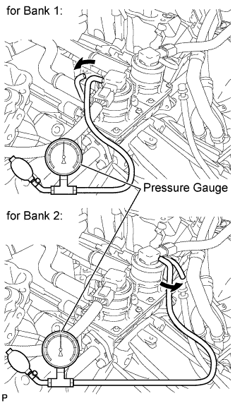 |
Connect a pressure gauge to the air pressure sensor as shown in the illustration.
Connect the Techstream to the DLC3.
Turn the ignition switch to ON.
Turn the Techstream on.
Enter the following menus: Powertrain / Engine and ECT / Data List / Air pump pressure (absolute) and Air Pump2 Pressure (Absolute).
Check that the pressure displayed on the Techstream fluctuates when applying the pressure to the pressure sensor with the pressure gauge.
|
| ||||
| OK | |
|
| 6.CHECK AIR INJECTION SYSTEM PIPE CONNECTIONS |
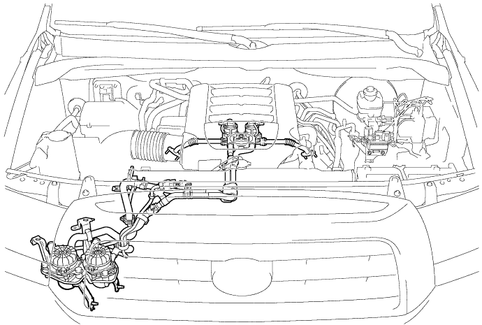
Check that all the pipes and hoses between the air pump and ASV are securely connected.
Inspect the pipes and hoses for blockages and damage.
|
| ||||
| OK | |
|
| 7.INSPECT AIR PUMP |
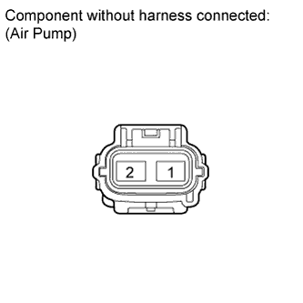 |
Disconnect the air pump connector.
Measure the resistance according to the value(s) in the table below.
| Tester Connection | Condition | Specified Condition |
| 1 - 2 | 20°C (68°F) | 0.44 to 1 Ω |
|
| ||||
| OK | |
|
| 8.INSPECT AIR INJECTION CONTROL DRIVER (AIR INJECTION CONTROL DRIVER POWER SOURCE CIRCUIT) |
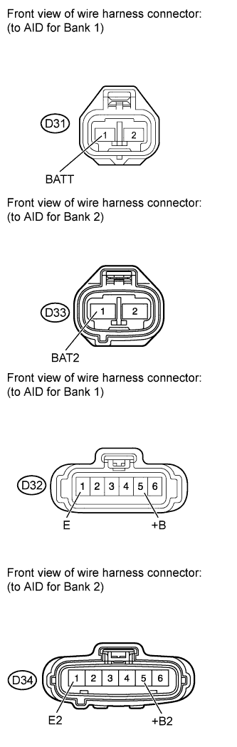 |
Disconnect the AID connectors.
Measure the resistance according to the value(s) in the table below.
| Tester Connection | Condition | Specified Condition |
| D32-1 (E) - Body ground | Always | Below 1 Ω |
| D34-1 (E2) - Body ground | Always | Below 1 Ω |
Turn the ignition switch to ON.
Measure the voltage according to the value(s) in the table below.
| Tester Connection | Switch Condition | Specified Condition |
| D31-1 (BATT) - Body ground | Always | 11 to 14 V (near battery voltage) |
| D32-5 (+B) - Body ground | Ignition switch ON | 11 to 14 V (near battery voltage) |
| D33-1 (BAT2) - Body ground | Always | 11 to 14 V (near battery voltage) |
| D34-5 (+B2) - Body ground | Ignition switch ON | 11 to 14 V (near battery voltage) |
|
| ||||
| OK | |
|
| 9.CHECK HARNESS AND CONNECTOR (ECM - AIR INJECTION CONTROL DRIVER) |
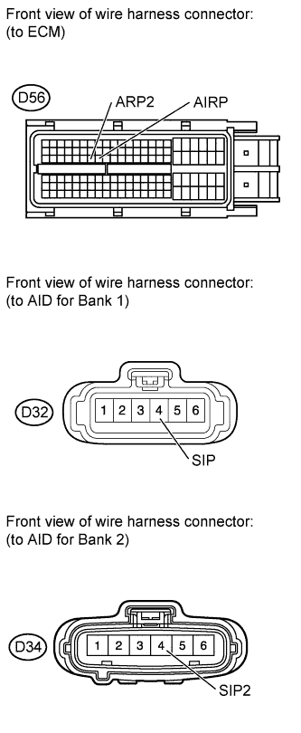 |
Disconnect the ECM connector.
Disconnect the AID connector.
Measure the resistance according to the value(s) in the table below.
| Tester Connection | Condition | Specified Condition |
| D56-54 (AIRP) - D32-4 (SIP) | Always | Below 1 Ω |
| D56-53 (ARP2) - D34-4 (SIP2) | Always | Below 1 Ω |
|
| ||||
| OK | |
|
| 10.REPLACE AIR INJECTION CONTROL DRIVER |
Replace the air injection control driver (Click here).
| NEXT | |
|
| 11.CHECK WHETHER DTC OUTPUT RECURS (DTC P2444, P2445, P2446 AND/OR P2447) |
Start the engine and warm it up.
Turn the ignition switch off.
Connect the Techstream to the DLC3.
Turn the ignition switch to ON.
Turn the Techstream on.
Clear DTCs (if set) (Click here).
Enter the following menus: Powertrain / Engine and ECT / Utility / Air injection check / Automatic Mode.
Start the engine after the Techstream initialization is finished.
Perform the System Check operation by pressing ENTER (Next).
After operating the AIR system, perform the following to confirm the AIR system pending codes: Press the Exit button.
Check pending DTCs.
Turn the ignition switch off.
|
| ||||
| OK | ||
 | ||
| ||
