 |
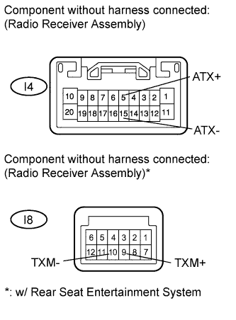
Disconnect the I4 and I8* radio receiver assembly connectors.
- HINT:
- *: w/ Rear Seat Entertainment System
AUDIO AND VISUAL SYSTEM > AVC-LAN Circuit |
| 1.INSPECT RADIO RECEIVER ASSEMBLY |
|
Disconnect the I4 and I8* radio receiver assembly connectors.
Measure the resistance according to the value(s) in the table below.
| Tester Connection | Condition | Specified Condition |
| I4-5 (ATX+) - I4-15 (ATX-) | Always | 60 to 80 Ω |
| I8-9 (TXM+) - I8-10 (TXM-)* | Always | 60 to 80 Ω |
Reconnect the radio receiver assembly connectors.
|
| ||||
| OK | |
 |
| 2.CHECK HARNESS AND CONNECTOR (RADIO RECEIVER - COMPONENT WHICH HAS STORED THIS CODE) |
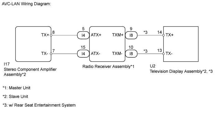
Referring to the AVC-LAN wiring diagram below, check all AVC-LAN circuits.
Disconnect all connectors in all AVC-LAN circuits.
Check for an open or short in all AVC-LAN circuits.
|
| ||||
| OK | ||
 | ||
| ||
