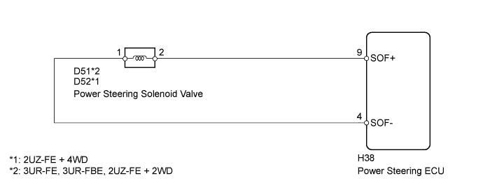
POWER STEERING SYSTEM > VFC Power Steering Solenoid Circuit |
| 1.CHECK HARNESS AND CONNECTOR (POWER STEERING SOLENOID VALVE - ECU) |
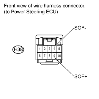 |
Disconnect the power steering ECU connector.
Measure the resistance according to the value(s) in the table below.
| Tester Connection | Condition | Specified Condition |
| H38-4 (SOF-) - H38-9 (SOF+) | 20°C (68°F) | 6.7 to 7.3 Ω |
| H38-4 (SOF-) - Body ground | Always | 10 kΩ or higher |
| H38-9 (SOF+) - Body ground | Always | 10 kΩ or higher |
|
| ||||
| OK | |
 |
| 2.INSPECT POWER STEERING SOLENOID VALVE |
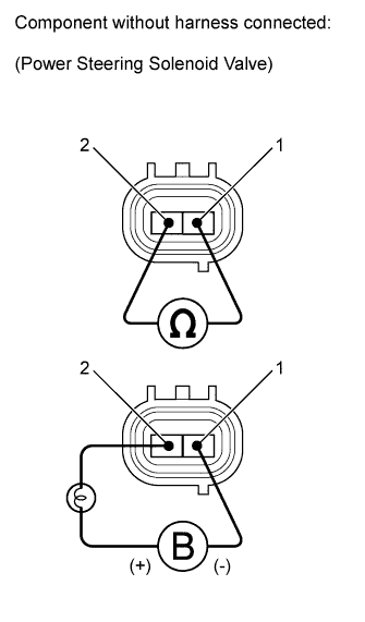 |
Disconnect the power steering solenoid valve connector.
Measure the resistance according to the value(s) in the table below.
| Tester Connection | Condition | Specified Condition |
| 1 - 2 | 20°C (68°F) | 6.7 to 7.3 Ω |
Connect the battery positive (+) lead with a 21 W bulb to terminal 2 and the negative (-) lead to terminal 1 of the solenoid valve connector. Then check that the valve moves and makes an operating noise.
| Result | Proceed to |
| OK | A |
| NG (3UR-FE, 3UR-FBE) | B |
| NG (2UZ-FE) | C |
|
| ||||
|
| ||||
| A | ||
 | ||
| ||
| 3.INSPECT POWER STEERING SOLENOID VALVE |
|
Disconnect the power steering solenoid valve connector.
Measure the resistance according to the value(s) in the table below.
| Tester Connection | Condition | Specified Condition |
| 1 - 2 | 20°C (68°F) | 6.7 to 7.3 Ω |
Connect the battery positive (+) lead with a 21 W bulb to terminal 2 and the negative (-) lead to terminal 1 of the solenoid valve connector. Then check that the valve moves and makes an operating noise.
| Result | Proceed to |
| OK | A |
| NG (3UR-FE, 3UR-FBE) | B |
| NG (2UZ-FE) | C |
|
| ||||
|
| ||||
| A | ||
| ||
| ||

