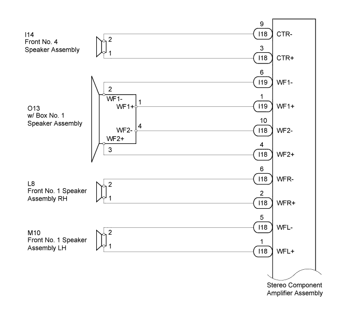
DTC 74-40 Short in Speaker Circuit |
| DTC Code | DTC Detection Condition | Trouble Area |
| 74-40 | A short is detected in the speaker output circuit. |
|
| 1.CHECK DTC |
Disconnect the I18 and I19 stereo component amplifier assembly connectors.
Clear the DTC.
Check if DTC 74-40 is output.
|
| ||||
| OK | |
 |
| 2.CHECK DTC |
Reconnect the I18 stereo component amplifier assembly connector.
Check if DTC 74-40 is output.
|
| ||||
| OK | |
|
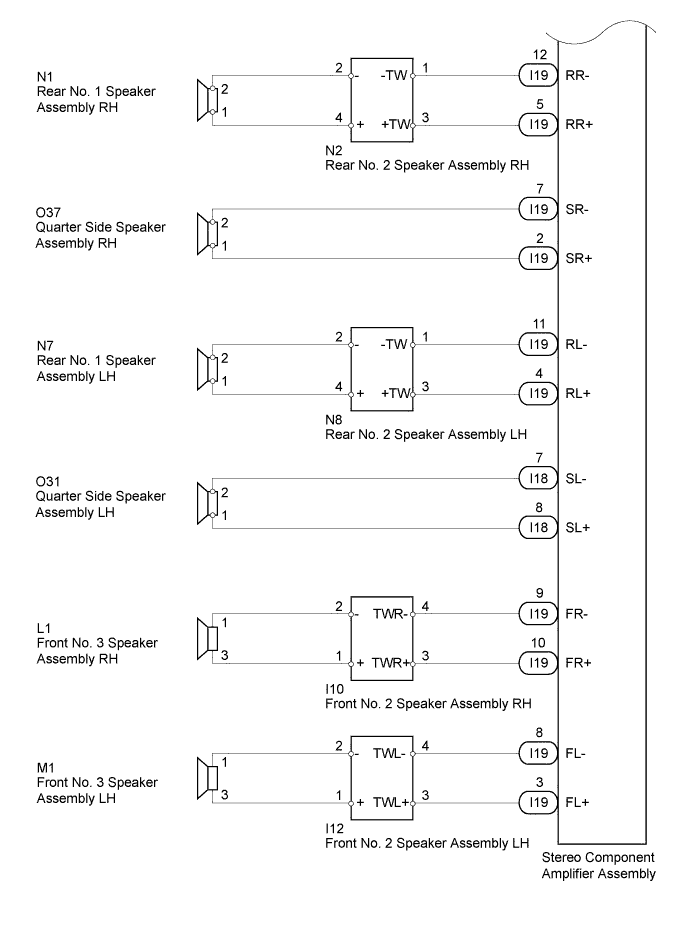
| 3.CHECK HARNESS AND CONNECTOR (STEREO COMPONENT AMPLIFIER ASSEMBLY - SPEAKER) |
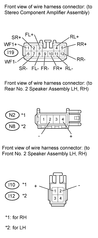 |
Disconnect the I19 stereo component amplifier assembly connector.
Disconnect the N2*1, N8*2, I10*1 and I12*2 speaker connectors.
Measure the resistance according to the value(s) in the table below.
| Tester Connection | Condition | Specified Condition |
| I19-6 (WF1-) - Body ground | Always | 10 kΩ or higher |
| I19-1 (WF1+) - Body ground | ||
| I19-12 (RR-) - Body ground | ||
| I19-5 (RR+) - Body ground | ||
| N2-2 (-) - Body ground | ||
| N2-4 (+) - Body ground | ||
| I19-7 (SR-) - Body ground | ||
| I19-2 (SR+) - Body ground | ||
| I19-11(RL-) - Body ground | ||
| I19-4 (RL+) - Body ground | ||
| N8-2 (-) - Body ground | ||
| N8-4 (+) - Body ground | ||
| I19-9 (FR-) - Body ground | ||
| I19-10 (FR+) - Body ground | ||
| I10-2 (-) - Body ground | ||
| I10-1 (+) - Body ground | ||
| I19-8 (FL-) - Body ground | ||
| I19-3 (FL+) - Body ground | ||
| I12-2 (-) - Body ground | ||
| I12-1 (+) - Body ground |
Reconnect the stereo component amplifier assembly connector.
Reconnect the speaker connectors.
|
| ||||
| OK | |
|
| 4.INSPECT REAR NO. 1 SPEAKER ASSEMBLY RH |
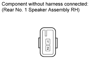 |
Disconnect the N1 speaker connector.
Measure the resistance according to the value(s) in the table below.
| Tester Connection | Condition | Specified Condition |
| 1 - 2 | Always | 1.8 to 2.6 Ω |
Reconnect the speaker connector.
|
| ||||
| OK | |
|
| 5.INSPECT REAR NO. 2 SPEAKER ASSEMBLY RH |
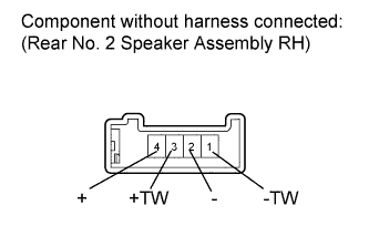 |
Disconnect the N2 speaker connector.
Measure the resistance according to the value(s) in the table below.
| Tester Connection | Condition | Specified Condition |
| 1 (-TW) - 3 (+TW) | Always | 3.0 to 4.2 Ω |
| 1 (-TW) - 2 (-) | Always | Below 1 Ω |
| 3 (+TW) - 4 (+) |
Reconnect the speaker connector.
|
| ||||
| OK | |
|
| 6.INSPECT QUARTER SIDE SPEAKER ASSEMBLY RH |
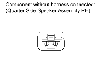 |
Disconnect the O37 speaker connector.
Measure the resistance according to the value(s) in the table below.
| Tester Connection | Condition | Specified Condition |
| 1 - 2 | Always | 1.5 to 2.5 Ω |
Reconnect the speaker connector.
|
| ||||
| OK | |
|
| 7.INSPECT REAR NO. 1 SPEAKER ASSEMBLY LH |
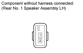 |
Disconnect the N7 speaker connector.
Measure the resistance according to the value(s) in the table below.
| Tester Connection | Condition | Specified Condition |
| 1 - 2 | Always | 1.8 to 2.6 Ω |
Reconnect the speaker connector.
|
| ||||
| OK | |
|
| 8.INSPECT REAR NO. 2 SPEAKER ASSEMBLY LH |
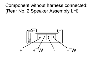 |
Disconnect the N8 speaker connector.
Measure the resistance according to the value(s) in the table below.
| Tester Connection | Condition | Specified Condition |
| 1 (-TW) - 3 (+TW) | Always | 3.0 to 4.2 Ω |
| 1 (-TW) - 2 (-) | Always | Below 1 Ω |
| 3 (+TW) - 4 (+) |
Reconnect the speaker connector.
|
| ||||
| OK | |
|
| 9.INSPECT FRONT NO. 3 SPEAKER ASSEMBLY RH |
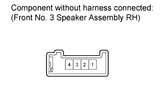 |
Disconnect the L1 speaker connector.
Measure the resistance according to the value(s) in the table below.
| Tester Connection | Condition | Specified Condition |
| 1 - 3 | Always | 3.0 to 4.2 Ω |
Reconnect the speaker connector.
|
| ||||
| OK | |
|
| 10.INSPECT FRONT NO. 2 SPEAKER ASSEMBLY RH |
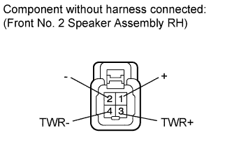 |
Disconnect the I10 speaker connector.
Measure the resistance according to the value(s) in the table below.
| Tester Connection | Condition | Specified Condition |
| 3 (TWR+) - 4 (TWR-) | Always | 1.5 to 2.5 Ω |
| 2 (-) - 4 (TWR-) | Always | Below 1 Ω |
| 1 (+) - 3 (TWR+) |
Reconnect the speaker connector.
|
| ||||
| OK | |
|
| 11.INSPECT FRONT NO. 3 SPEAKER ASSEMBLY LH |
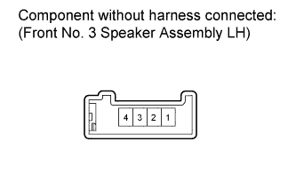 |
Disconnect the M1 speaker connector.
Measure the resistance according to the value(s) in the table below.
| Tester Connection | Condition | Specified Condition |
| 1 - 3 | Always | 3.0 to 4.2 Ω |
Reconnect the speaker connector.
|
| ||||
| OK | |
|
| 12.INSPECT FRONT NO. 2 SPEAKER ASSEMBLY LH |
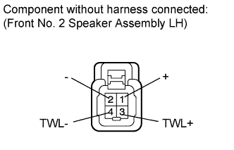 |
Disconnect the I12 speaker connector.
Measure the resistance according to the value(s) in the table below.
| Tester Connection | Condition | Specified Condition |
| 3 (TWL+) - 4 (TWL-) | Always | 1.5 to 2.5 Ω |
| 2 (-) - 4 (TWL-) | Always | Below 1 Ω |
| 1 (+) - 3 (TWL+) |
Reconnect the speaker connector.
|
| ||||
| OK | ||
 | ||
| ||
| 13.CHECK HARNESS AND CONNECTOR (STEREO COMPONENT AMPLIFIER ASSEMBLY - SPEAKER) |
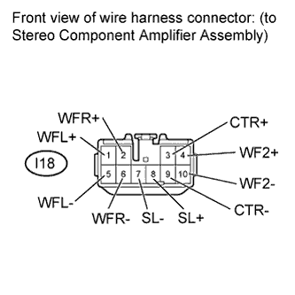 |
Disconnect the I18 stereo component amplifier assembly connector.
Measure the resistance according to the value(s) in the table below.
| Tester Connection | Condition | Specified Condition |
| I18-7 (SL-) - Body ground | Always | 10 kΩ or higher |
| I18-8 (SL+) - Body ground | ||
| I18-9 (CTR-) - Body ground | ||
| I18-3 (CTR+) - Body ground | ||
| I18-10 (WF2-) - Body ground | ||
| I18-4 (WF2+) - Body ground | ||
| I18-6 (WFR-) - Body ground | ||
| I18-2 (WFR+) - Body ground | ||
| I18-5 (WFL-) - Body ground | ||
| I18-1 (WFL+) - Body ground |
Reconnect the stereo component amplifier assembly connector.
|
| ||||
| OK | |
|
| 14.INSPECT QUARTER SIDE SPEAKER ASSEMBLY LH |
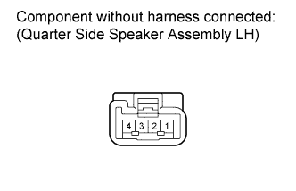 |
Disconnect the O31 speaker connector.
Measure the resistance according to the value(s) in the table below.
| Tester Connection | Condition | Specified Condition |
| 1 - 2 | Always | 1.5 to 2.5 Ω |
Reconnect the speaker connector.
|
| ||||
| OK | |
|
| 15.INSPECT FRONT NO. 1 SPEAKER ASSEMBLY RH |
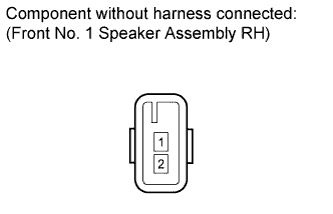 |
Disconnect the L8 speaker connector.
Measure the resistance according to the value(s) in the table below.
| Tester Connection | Condition | Specified Condition |
| 1 - 2 | Always | 1.8 to 2.6 Ω |
Reconnect the speaker connector.
|
| ||||
| OK | |
|
| 16.INSPECT FRONT NO. 1 SPEAKER ASSEMBLY LH |
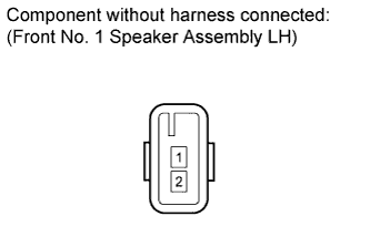 |
Disconnect the M10 speaker connector.
Measure the resistance according to the value(s) in the table below.
| Tester Connection | Condition | Specified Condition |
| 1 - 2 | Always | 1.8 to 2.6 Ω |
Reconnect the speaker connector.
|
| ||||
| OK | |
|
| 17.INSPECT FRONT NO. 4 SPEAKER ASSEMBLY |
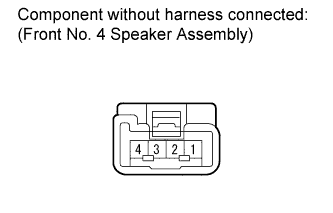 |
Disconnect the I14 speaker connector.
Measure the resistance according to the value(s) in the table below.
| Tester Connection | Condition | Specified Condition |
| 1 - 2 | Always | 1.5 to 2.1 Ω |
Reconnect the speaker connector.
|
| ||||
| OK | ||
| ||
| ||

