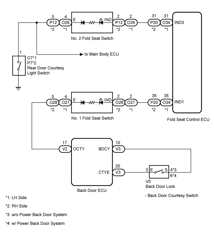
REAR POWER SEAT CONTROL SYSTEM > Indicator Circuit |
| 1.CONFIRM INDICATOR CIRCUIT |
Perform troubleshooting in accordance with the chart below.
| Result | Proceed to |
| No. 1 fold seat switch indicator circuit | A |
| No. 2 fold seat switch indicator circuit | B |
|
| ||||
| A | |
 |
| 2.READ VALUE USING TECHSTREAM (BACK DOOR COURTESY SWITCH) |
Connect the Techstream to the DLC3.
Turn the ignition switch to ON.
Turn the Techstream ON.
Enter the following menus: Body Electrical / Back Door P/W / Data List.
According to the display on the Techstream, read the Data List.
| Tester Display | Measurement Item/Range | Normal Condition | Diagnostic Note |
| Back Door Courtesy Switch | Back Door Courtesy Switch / ON or OFF | ON: Back door opened OFF: Back door closed | - |
|
| ||||
| OK | |
|
| 3.INSPECT NO. 1 FOLD SEAT SWITCH |
Remove the No. 1 fold seat switch (Click here).
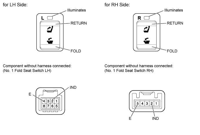
Apply battery voltage to the switch connector, and check that the fold seat switch assembly illuminates.
| Measurement Condition | Switch Condition | Specified Condition |
| Battery positive (+) → 2 (IND) Battery negative (-) → 4 (E) | FOLD | Illuminates |
| RETURN | Illuminates |
| Measurement Condition | Switch Condition | Specified Condition |
| Battery positive (+) → 2 (IND) Battery negative (-) → 5 (E) | FOLD | Illuminates |
| RETURN | Illuminates |
|
| ||||
| OK | |
|
| 4.CHECK HARNESS AND CONNECTOR (BACK DOOR ECU - NO. 1 FOLD SEAT SWITCH) |
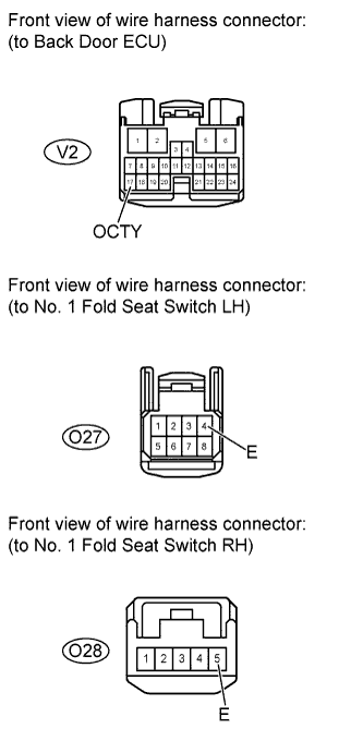 |
Disconnect the V2 ECU connector.
Disconnect the O27 or O28 switch connector.
Measure the resistance according to the value(s) in the table below.
| Tester Connection | Condition | Specified Condition |
| V2-17 (OCTY) - O27-4 (E) | Always | Below 1 Ω |
| V2-17 (OCTY) - Body ground | Always | 10 kΩ or higher |
| Tester Connection | Condition | Specified Condition |
| V2-17 (OCTY) - O28-5 (E) | Always | Below 1 Ω |
| V2-17 (OCTY) - Body ground | Always | 10 kΩ or higher |
|
| ||||
| OK | |
|
| 5.CHECK HARNESS AND CONNECTOR (FOLD SEAT CONTROL ECU - NO. 1 FOLD SEAT SWITCH) |
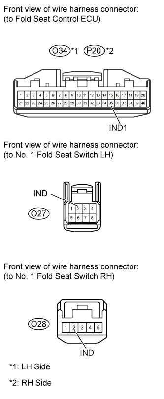 |
Disconnect the O34 or P20 ECU connector.
Disconnect the O27 or O28 switch connector.
Measure the resistance according to the value(s) in the table below.
| Tester Connection | Condition | Specified Condition |
| O34-35 (IND1) - O27-2 (IND) | Always | Below 1 Ω |
| O34-35 (IND1) - Body ground | Always | 10 kΩ or higher |
| Tester Connection | Condition | Specified Condition |
| P20-35 (IND1) - O28-2 (IND) | Always | Below 1 Ω |
| P20-35 (IND1) - Body ground | Always | 10 kΩ or higher |
|
| ||||
| OK | ||
 | ||
| ||
| 6.READ VALUE USING TECHSTREAM (REAR DOOR COURTESY SWITCH) |
Connect the Techstream to the DLC3.
Turn the ignition switch to ON.
Turn the Techstream ON.
Enter the following menus: Body Electrical / Main Body / Data List.
According to the display on the Techstream, read the Data List.
| Tester Display | Measurement Item/Range | Normal Condition | Diagnostic Note |
| RL Door Courtesy SW | Rear door courtesy light switch LH signal / ON or OFF | ON: Rear door courtesy light switch LH ON OFF: Rear door courtesy light switch LH OFF | - |
| RR Door Courtesy SW | Rear door courtesy light switch RH signal / ON or OFF | ON: Rear door courtesy light switch RH ON OFF: Rear door courtesy light switch RH OFF | - |
|
| ||||
| OK | |
|
| 7.INSPECT NO. 2 FOLD SEAT SWITCH |
Remove the No. 2 fold seat switch (Click here).
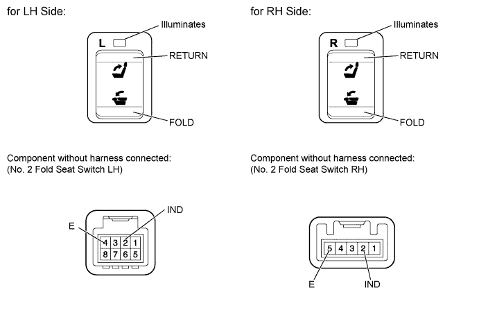
Apply battery voltage to the switch connector, and check that the fold seat switch assembly illuminates.
| Measurement Condition | Switch Condition | Specified Condition |
| Battery positive (+) → 2 (IND) Battery negative (-) → 4 (E) | FOLD | Illuminates |
| RETURN | Illuminates |
| Measurement Condition | Switch Condition | Specified Condition |
| Battery positive (+) → 2 (IND) Battery negative (-) → 5 (E) | FOLD | Illuminates |
| RETURN | Illuminates |
|
| ||||
| OK | |
|
| 8.CHECK HARNESS AND CONNECTOR (REAR DOOR COURTESY LIGHT SWITCH - NO. 2 FOLD SEAT SWITCH) |
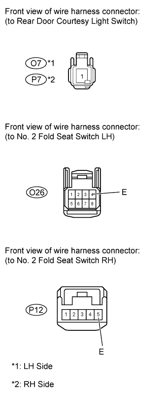 |
Disconnect the O7 or P7 switch connector.
Disconnect the O26 or P12 switch connector.
Measure the resistance according to the value(s) in the table below.
| Tester Connection | Condition | Specified Condition |
| O7-1 - O26-4 (E) | Always | Below 1 Ω |
| O7-1 - Body ground | Always | 10 kΩ or higher |
| Tester Connection | Condition | Specified Condition |
| P7-1 - P12-5 (E) | Always | Below 1 Ω |
| P7-1 - Body ground | Always | 10 kΩ or higher |
|
| ||||
| OK | |
|
| 9.CHECK HARNESS AND CONNECTOR (FOLD SEAT CONTROL ECU - NO. 2 FOLD SEAT SWITCH) |
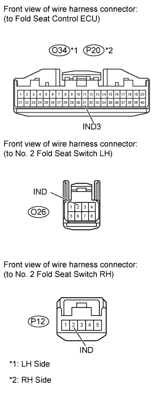 |
Disconnect the O34 or P20 ECU connector.
Disconnect the O26 or P12 switch connector.
Measure the resistance according to the value(s) in the table below.
| Tester Connection | Condition | Specified Condition |
| O34-31 (IND3) - O26-2 (IND) | Always | Below 1 Ω |
| O34-31 (IND3) - Body ground | Always | 10 kΩ or higher |
| Tester Connection | Condition | Specified Condition |
| P20-31 (IND3) - P12-2 (IND) | Always | Below 1 Ω |
| P20-31 (IND3) - Body ground | Always | 10 kΩ or higher |
|
| ||||
| OK | ||
| ||
| ||

