 |
Loosen the hose clamp and disconnect the air cleaner from the air cleaner hose.
OIL PUMP > REMOVAL |
| 1. DISCHARGE FUEL SYSTEM PRESSURE |
| 2. DRAIN ENGINE OIL |
Remove the oil filler cap.
Remove the oil pan drain plug and gasket, and drain the engine oil into a container.
Install a new gasket and the oil pan drain plug.
| 3. REMOVE RADIATOR ASSEMBLY |
Remove the radiator (Click here).
| 4. REMOVE AIR CLEANER ASSEMBLY |
|
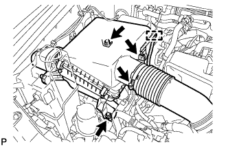
Loosen the hose clamp and disconnect the air cleaner from the air cleaner hose.
Loosen the 2 bolts and remove the air cleaner with the grommet.
| 5. REMOVE AIR CLEANER HOSE ASSEMBLY |
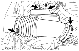 |
Disconnect the vacuum hose and ventilation hose.
Loosen the 2 clamps.
Remove the air cleaner hose.
| 6. DISCONNECT INLET HEATER WATER HOSE C |
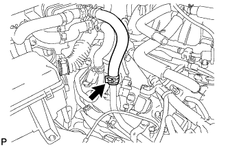 |
Disconnect the inlet heater water hose from the No. 1 water by-pass pipe.
| 7. DISCONNECT OUTLET HEATER WATER HOSE C |
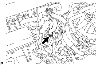 |
Disconnect the outlet heater water hose from the water by-pass pipe.
| 8. SEPARATE ENGINE WIRE |
| 9. SEPARATE NO. 2 ENGINE WIRE |
| 10. REMOVE INTAKE MANIFOLD |
Remove the intake manifold (Click here).
| 11. DISCONNECT NO. 3 AIR INJECTION SYSTEM HOSE |
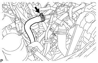 |
Disconnect the No. 3 air injection hose.
| 12. DISCONNECT NO. 2 AIR INJECTION SYSTEM HOSE |
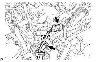 |
Disconnect the connector and separate the wire harness clamp.
Disconnect the No. 2 air injection hose.
| 13. SEPARATE COOLER COMPRESSOR ASSEMBLY |
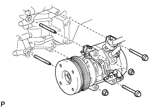 |
Remove the 2 bolts, 2 nuts and 2 stud bolts, and disconnect the cooler compressor.
| 14. SEPARATE NO. 2 FUEL TUBE SUB-ASSEMBLY |
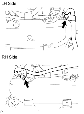 |
Remove the 2 bolts and separate the fuel tube.
| 15. REMOVE OIL FILTER ELEMENT |
Remove the oil filter element (Click here).
| 16. REMOVE OIL PRESSURE SENDER GAUGE ASSEMBLY (w/o Trailer Towing System) |
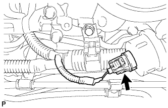 |
Disconnect the sender gauge connector.
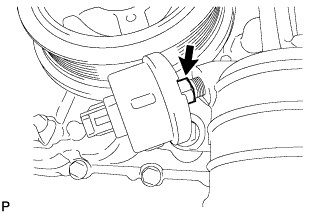 |
Remove the oil pressure sender gauge.
| 17. REMOVE ENGINE OIL COOLER (w/ Trailer Towing System) |
Remove the engine oil cooler (Click here).
| 18. REMOVE OIL FILTER BRACKET (w/o Trailer Towing System) |
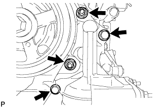 |
Remove the 2 bolts, 2 nuts and filter bracket.
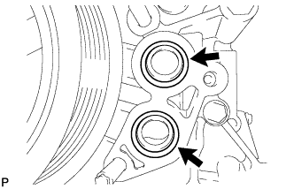 |
Remove the 2 O-rings.
| 19. REMOVE ENGINE OIL LEVEL DIPSTICK GUIDE |
Remove the dipstick.
Disconnect the wire harness clamp.
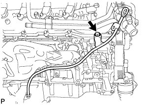 |
Remove the bolt and dipstick guide.
Remove the O-ring from the dipstick guide.
| 20. REMOVE GENERATOR ASSEMBLY |
Remove the generator assembly (Click here).
| 21. REMOVE NO. 1 WATER BY-PASS HOSE |
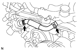 |
Remove the No. 1 water by-pass hose by disconnect the hose from the water inlet housing and front water by-pass joint.
| 22. SEPARATE AIR PIPE SUB-ASSEMBLY |
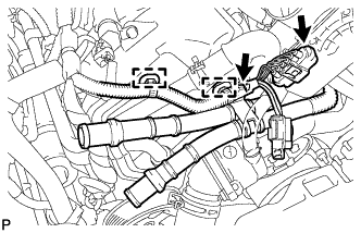 |
Disconnect the connector and separate the 2 clamps and wire harness.
Remove bolt and separate the air pipe.
| 23. REMOVE WATER BY-PASS PIPE SUB-ASSEMBLY |
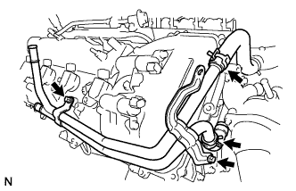 |
Disconnect the 2 hoses.
Remove the 2 bolts and water by-pass pipe.
| 24. SEPARATE NO. 1 WATER BY-PASS PIPE |
Remove the 2 bolts and separate the No. 1 water by-pass pipe.
| 25. REMOVE FRONT WATER BY-PASS JOINT |
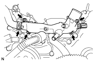 |
Disconnect the No. 2 water by-pass hose from the water by-pass joint.
Remove the 4 nuts, water by-pass joint and 2 gaskets.
| 26. REMOVE NO. 2 CYLINDER HEAD COVER |
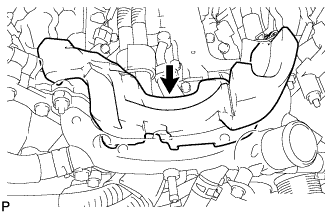 |
Remove the No. 2 cylinder head cover.
| 27. REMOVE NO. 1 ENGINE COVER |
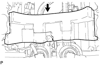 |
Remove the No. 1 engine cover.
| 28. REMOVE AIR PIPE SUB-ASSEMBLY |
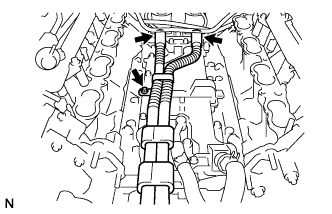 |
Remove the bolt, disconnect the 2 hoses, and remove the air pipe.
| 29. REMOVE WATER INLET HOUSING |
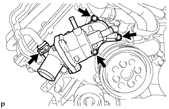 |
Remove the 3 bolts and water inlet housing and disconnect the No. 3 water by-pass hose from the water inlet housing.
Remove the gasket from the water pump.
| 30. REMOVE WATER PUMP PULLEY |
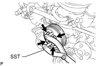 |
Using SST, hold the water pump pulley.
Remove the 4 bolts and water pump pulley.
| 31. REMOVE NO. 1 IDLER PULLEY SUB-ASSEMBLY |
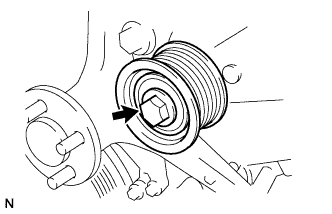 |
Remove the bolt and idler pulley.
| 32. REMOVE FLUID COUPLING BRACKET |
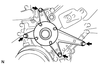 |
Remove the 4 bolts and fluid coupling bracket.
| 33. REMOVE V-RIBBED BELT TENSIONER ASSEMBLY |
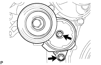 |
Remove the standard bolt, 6 mm hexagon wrench bolt and belt tensioner.
| 34. REMOVE IGNITION COIL ASSEMBLY |
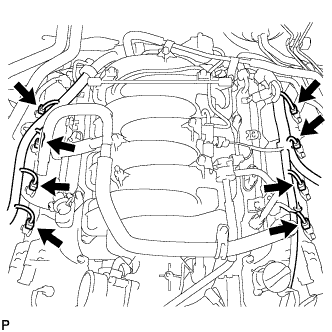 |
Disconnect the 8 ignition coil connectors.
Remove the 8 bolts and 8 ignition coils.
| 35. REMOVE CYLINDER HEAD COVER SUB-ASSEMBLY LH |
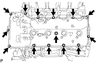 |
Remove the 14 bolts, seal washer, cylinder head cover and gasket.
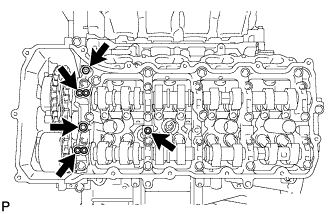 |
Remove the 5 O-rings from the camshaft bearing caps (No. 2, No. 3).
| 36. REMOVE RADIO SETTING CONDENSER (for Bank 2) |
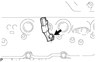 |
Remove the bolt and noise filter.
| 37. REMOVE CYLINDER HEAD COVER SUB-ASSEMBLY |
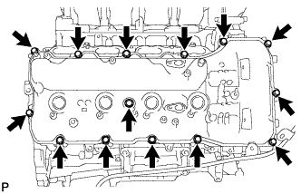 |
Remove the 14 bolts, seal washer, cylinder head cover and gasket.
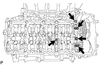 |
Remove the 5 O-rings from the camshaft bearing caps (No. 1, No. 3).
| 38. REMOVE CRANKSHAFT PULLEY |
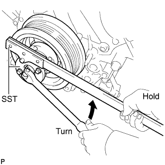 |
Using SST, loosen the crankshaft pulley set bolt.
Partially install the pulley set bolt to the crankshaft until 2 or 3 threads are engaged.
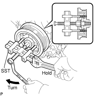 |
Using the pulley set bolt and SST, remove the crankshaft pulley.
| 39. DISCONNECT WIRE HARNESS CLAMP BRACKET |
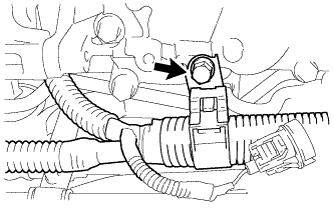 |
Remove the bolt and disconnect the bracket.
| 40. REMOVE CRANKSHAFT TIMING GEAR KEY |
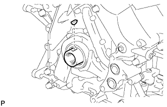 |
Using a screwdriver, remove the timing gear key from the crankshaft.
| 41. REMOVE TIMING CHAIN COVER SUB-ASSEMBLY |
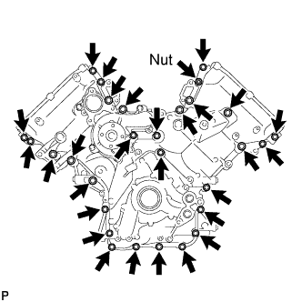 |
Remove the 28 bolts and nut shown in the illustration.
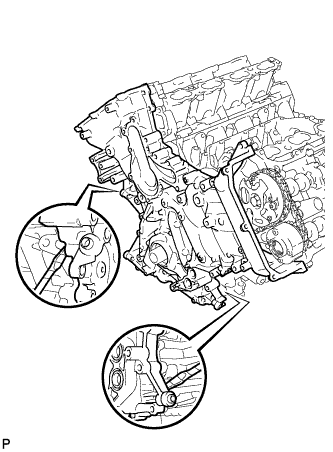 |
Remove the timing chain cover by prying between it and the cylinder head and cylinder block with a screwdriver as shown in the illustration.
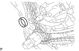 |
Remove the oil pump gasket from the cylinder block.
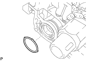 |
Remove the O-ring from the oil pan.
| 42. REMOVE WATER INLET PIPE |
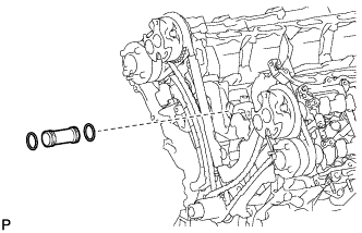 |
Remove the water inlet pipe.
Remove the 2 O-rings from the water inlet pipe.