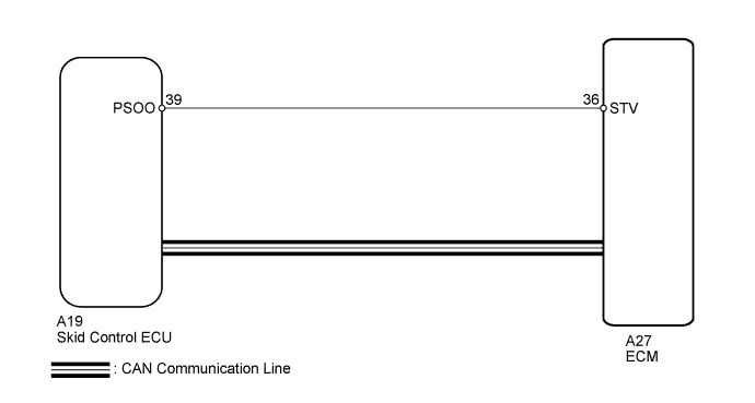
DTC P0575 Cruise Control Input Circuit |
| DTC Code | DTC Detection Condition | Trouble Area |
| P0575 | When STV signal is input and cruise control continues for 0.4 seconds. When malfunction STV signal is detected for 0.15 seconds. |
|
| 1.CHECK FOR DTC (IN VEHICLE STABILITY CONTROL SYSTEM) |
Check for DTCs in Vehicle Stability Control System (Click here).
| Result | Proceed to |
| DTC is not output | A |
| DTC is out put | B |
|
| ||||
| A | |
 |
| 2.CHECK HARNESS AND CONNECTOR (SKID CONTROL ECU - ECM) |
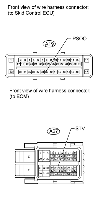 |
Disconnect the A27 connector from the ECM.
Disconnect the A19 connector the ECU.
Measure the resistance according to the value(s) in the table below.
| Tester Connection | Condition | Specified Condition |
| A19-39 (PSOO) - A27-36 (STV) | Always | Below 1 Ω |
| A19-39 (PSOO) or A27-36 (STV) - Body ground | Always | 10 kΩ or higher |
Reconnect the ECM and ECU connector.
| Result | Proceed to |
| NG | A |
| OK (for 2UZ-FE) | B |
| OK (for 3UR-FE) | C |
| OK (for 3UR-FBE) | D |
|
| ||||
|
| ||||
|
| ||||
| A | ||
 | ||
| ||
