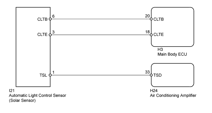
DTC B1424/24 Solar Sensor Circuit (Driver Side) |
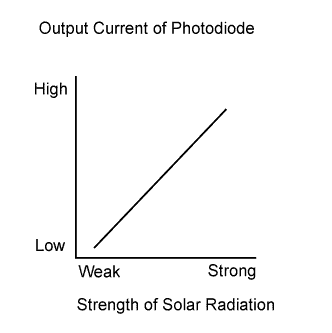
| DTC Code | DTC Detection Condition | Trouble Area |
| B1424/24 | Open or short in driver side solar sensor circuit |
|
| 1.READ VALUE USING TECHSTREAM (SOLAR SENSOR (D SIDE)) |
Connect the Techstream to the DLC3.
Turn the ignition switch to ON.
Turn the Techstream on.
Enter the following menus: Body Electrical / Air Conditioner / Data List / Solar Senor (D Side).
According to the display on the Techstream, read the Data List.
| Tester Display | Measurement Item/Range | Normal Condition | Diagnostic Note |
| Solar Sensor (D Side) | Driver side solar sensor / Min.: 0 Max.: 255 | Driver side solar sensor voltage increases as brightness increases | Open in circuit: 0 Short in circuit: 255 |
| Result | Proceed to |
| NG | A |
| OK (When troubleshooting according to Problem Symptoms Table) | B |
| OK (When troubleshooting according to the DTC output) | C |
|
| ||||
|
| ||||
| A | |
 |
| 2.CHECK HARNESS AND CONNECTOR (SOLAR SENSOR) |
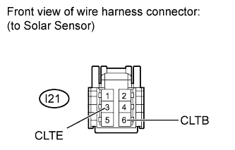 |
Disconnect the I21 automatic light control sensor (solar sensor) connector.
Measure the resistance according to the value(s) in the table below.
| Tester Connection | Condition | Specified Condition |
| I21-3 (CLTE) - Body ground | Always | Below 1 Ω |
Measure the voltage according to the value(s) in the table below.
| Tester Connection | Switch Condition | Specified Condition |
| I21-6 (CLTB) - I21-3 (CLTE) | Ignition switch ON | 11 to 14 V |
| Ignition switch off | Below 1 V |
Reconnect the automatic light control sensor (solar sensor) connector.
|
| ||||
| OK | |
|
| 3.CHECK HARNESS AND CONNECTOR (AIR CONDITIONING AMPLIFIER - SOLAR SENSOR) |
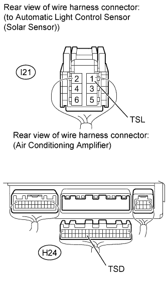 |
Disconnect the H24 air conditioning amplifier connector.
Disconnect the I21 automatic light control sensor (solar sensor) connector.
Measure the resistance according to the value(s) in the table below.
| Tester Connection | Condition | Specified Condition |
| H24-33 (TSD) - I21-1 (TSL) | Always | Below 1 Ω |
| H24-33 (TSD) or I21-1 (TSL) - Body ground | Always | 10 kΩ or higher |
Reconnect the automatic light control sensor (solar sensor) connector.
Reconnect the air conditioning amplifier connector.
|
| ||||
| OK | |
|
| 4.CHECK AUTOMATIC LIGHT CONTROL SENSOR (SOLAR SENSOR (TSL - CLTE VOLTAGE)) |
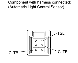 |
Remove the automatic light control sensor (solar sensor) with its connector still connected (Click here).
Apply battery voltage between terminals 6 (CLTB) and 3 (CLTE) of the solar sensor.
Measure the voltage according to the value(s) in the table below.
| Tester Connection | Condition | Specified Condition |
| 1 (TSL) - 3 (CLTE) | Sensor is subjected to electric light | 0.8 to 4.3 V |
| Sensor is covered with a cloth | Below 0.8 V |
Reinstall the automatic light control sensor (solar sensor).
|
| ||||
| OK | ||
 | ||
| ||
| 5.CHECK HARNESS AND CONNECTOR (MAIN BODY ECU - SOLAR SENSOR, BODY GROUND) |
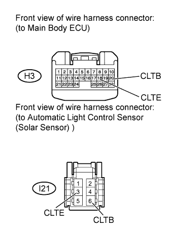 |
Disconnect the H3 main body ECU connector.
Disconnect the I21 automatic light control sensor (solar sensor) connector.
Measure the resistance according to the value(s) in the table below.
| Tester Connection | Condition | Specified Condition |
| H3-18 (CLTE) - I21-3 (CLTE) | Always | Below 1 Ω |
| H3-20 (CLTB) - I21-6 (CLTB) | Always | Below 1 Ω |
| H3-18 (CLTE) or I21-3 (CLTE) - Body ground | Always | 10 kΩ or higher |
| H3-20 (CLTB) or I21-6 (CLTB) - Body ground | Always | 10 kΩ or higher |
Reconnect the automatic light control sensor (solar sensor) connector.
Reconnect the main body ECU connector.
|
| ||||
| OK | ||
| ||
| ||

