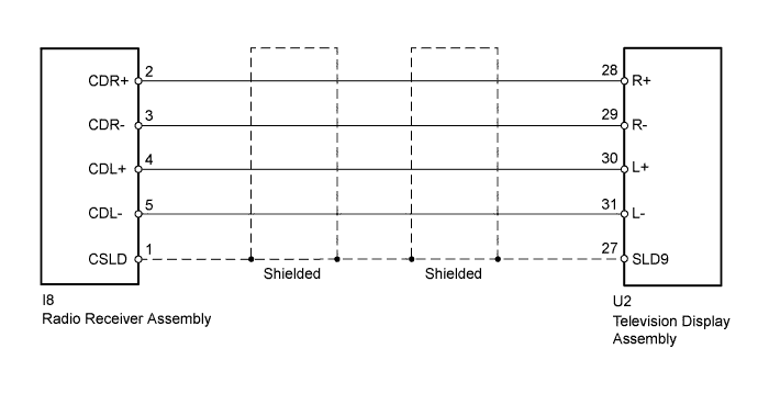
REAR SEAT ENTERTAINMENT SYSTEM > Sound Signal Circuit between Radio Receiver and Television Display Assembly |
| 1.CHECK HARNESS AND CONNECTOR (TELEVISION DISPLAY ASSEMBLY - RADIO RECEIVER ASSEMBLY) |
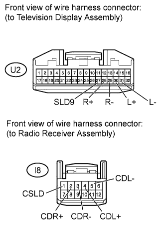 |
Disconnect the U2 television display assembly connector.
Disconnect the I8 radio receiver assembly connector.
Measure the resistance according to the value(s) in the table below.
| Tester Connection | Condition | Specified Condition |
| U2-28 (R+) - I8-2 (CDR+) | Always | Below 1 Ω |
| U2-29 (R-) - I8-3 (CDR-) | ||
| U2-30 (L+) - I8-4 (CDL+) | ||
| U2-31 (L-) - I8-5 (CDL-) | ||
| U2-27 (SLD9) - I8-1 (CSLD) | ||
| U2-28 (R+) - Body ground | Always | 10 kΩ or higher |
| U2-29 (R-) - Body ground | ||
| U2-30 (L+) - Body ground | ||
| U2-31 (L-) - Body ground | ||
| U2-27 (SLD9) - Body ground |
Reconnect the television display assembly connector.
Reconnect the radio receiver assembly connector.
|
| ||||
| OK | |
 |
| 2.INSPECT TELEVISION DISPLAY ASSEMBLY |
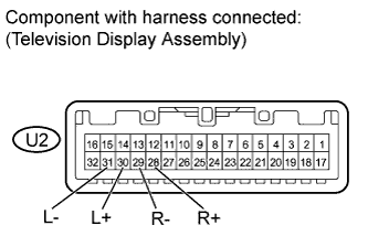 |
Reconnect the U2 television display assembly connector.
Using an oscilloscope, check the waveform between each terminal and the body ground according to the conditions, as shown in the table below.
| Tester Connection | Condition | Specified Condition |
| U2-28 (R+) - Body ground | Audio sound is being produced | A waveform synchronized with sound is output |
| U2-29 (R-) - Body ground | ||
| U2-30 (L+) - Body ground | ||
| U2-31 (L-) - Body ground |
Reconnect the television display assembly connector.
|
| ||||
| OK | ||
 | ||
| ||
