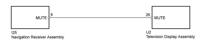
REAR SEAT ENTERTAINMENT SYSTEM > Mute Signal Circuit between Navigation Receiver Assembly and Television Display Assembly |
| 1.CHECK HARNESS AND CONNECTOR (TELEVISION DISPLAY - NAVIGATION RECEIVER) |
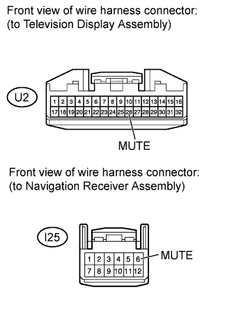 |
Disconnect the U2 television display assembly connector.
Disconnect the I25 navigation receiver assembly connector.
Measure the resistance according to the value(s) in the table below.
| Tester Connection | Condition | Specified Condition |
| U2-26 (MUTE) - I25-6 (MUTE) | Always | Below 1 Ω |
| U2-26 (MUTE) - Body ground | Always | 10 kΩ or higher |
Reconnect the television display assembly connector.
Reconnect the navigation receiver assembly connector.
|
| ||||
| OK | |
 |
| 2.INSPECT TELEVISION DISPLAY ASSEMBLY |
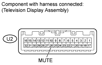 |
Measure the voltage according to the value(s) in the table below.
| Tester Connection | Switch Condition | Specified Condition |
| U2-26 (MUTE) - Body ground | Ignition switch ACC, television display is playing → Changing modes | 3.5 V or higher → Below 1 V |
|
| ||||
| OK | ||
 | ||
| ||
