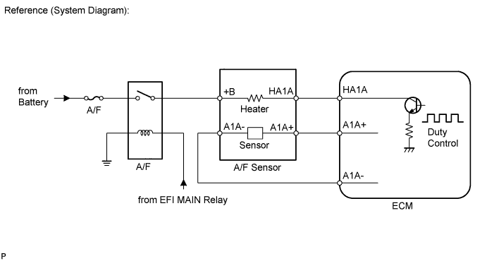
DTC P0031 Oxygen (A/F) Sensor Heater Control Circuit Low (Bank 1 Sensor 1) |
DTC P0032 Oxygen (A/F) Sensor Heater Control Circuit High (Bank 1 Sensor 1) |
DTC P0051 Oxygen (A/F) Sensor Heater Control Circuit Low (Bank 2 Sensor 1) |
DTC P0052 Oxygen (A/F) Sensor Heater Control Circuit High (Bank 2 Sensor 1) |
DTC P101D A/F Sensor Heater Circuit Performance Bank 1 Sensor 1 Stuck ON |
DTC P103D A/F Sensor Heater Circuit Performance Bank 2 Sensor 1 Stuck ON |
| DTC No. | DTC Detection Condition | Trouble Area |
| P0031 P0051 | Air-Fuel Ratio (A/F) sensor heater current is less than 0.8 A (1 trip detection logic) |
|
| P0032 P0052 | Air-Fuel Ratio (A/F) sensor heater current failure (1 trip detection logic) |
|
| P101D P103D | The heater current is higher than the specified value while the heater is not operating (1 trip detection logic). | ECM |
| Related DTCs | P0031: A/F sensor heater (for Bank 1) open/short (Low electrical current) P0032: A/F sensor heater (for Bank 1) open/short (High electrical current) P0051: A/F sensor heater (for Bank 2) open/short (Low electrical current) P0052: A/F sensor heater (for Bank 2) open/short (High electrical current) P101D: A/F sensor heater (for Bank 1) performance P103D: A/F sensor heater (for Bank 2) performance |
| Required Sensors/Components (Main) | A/F sensor heater |
| Required Sensors/Components (Related) | - |
| Frequency of Operation | Continuous |
| Duration | 11 seconds |
| MIL Operation | Immediate |
| Sequence of Operation | None |
| Monitor runs whenever following DTCs not stored | P101D, P103D (Air fuel ratio sensor heater) |
| Battery voltage | 10.5 V or higher |
| Time after engine start | 10 seconds or more |
| A/F sensor heater duty-cycle | 10% or more |
| Monitor runs whenever following DTCs not stored | None |
| Battery voltage | 10.5 V or higher |
| Time after engine start | 5 seconds or more |
| A/F sensor heater duty-cycle | More than 0% |
| Monitor runs whenever following DTCs not stored | P0031, P0051 (Air fuel ratio sensor heater) |
| Battery voltage | 10.5 V or higher |
| Time after engine start | 5 seconds or more |
| A/F sensor heater duty-cycle | 10 to 60% |
| A/F sensor heater ON current | 0.8 A or higher |
| A/F sensor heater current | Less than 0.8 A |
| Hybrid IC high current limiter port | Fail |
| Hybrid IC high current limiter port | Fail |
| A/F sensor heater current | 0.8 A or more |
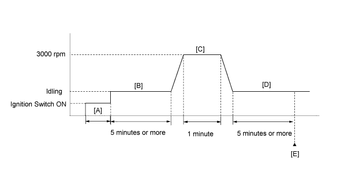
| Tester Display | Description |
| NORMAL |
|
| ABNORMAL |
|
| INCOMPLETE |
|
| N/A |
|
| 1.INSPECT AIR FUEL RATIO SENSOR (HEATER RESISTANCE) |
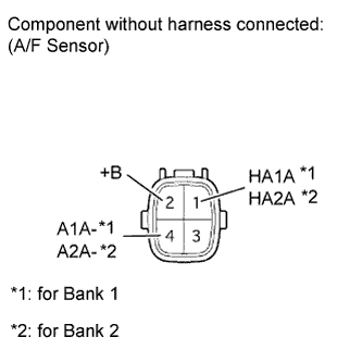 |
Disconnect the D19 or D20 A/F sensor connector.
Measure the resistance according to the value(s) in the table below.
| Tester Connection | Condition | Specified Condition |
| 1 (HA1A) - 2 (+B) | 20°C (68°F) | 1.6 to 3.2 Ω |
| 1 (HA1A) - 4 (A1A-) | Always | 10 kΩ or higher |
| 1 (HA2A) - 2 (+B) | 20°C (68°F) | 1.6 to 3.2 Ω |
| 1 (HA2A) - 4 (A2A-) | Always | 10 kΩ or higher |
|
| ||||
| OK | |
 |
| 2.CHECK TERMINAL VOLTAGE (+B OF A/F SENSOR) |
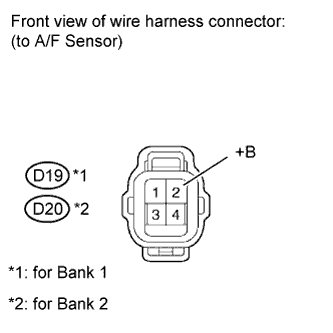 |
Disconnect the D19 or D20 A/F sensor connector.
Turn the ignition switch to ON.
Measure the voltage according to the value(s) in the table below.
| Tester Connection | Switch Condition | Specified Condition |
| D19-2 (+B) - Body ground | Ignition switch ON | 11 to 14 V |
| D20-2 (+B) - Body ground | Ignition switch ON | 11 to 14 V |
| Result | Proceed to |
| NG | A |
| OK | B |
|
| ||||
| A | |
|
| 3.INSPECT INTEGRATION RELAY (A/F) |
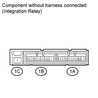 |
Remove the integration relay from the engine room relay block .
Inspect the A/F fuse.
Remove the A/F fuse from the integration relay.
Measure the resistance according to the value(s) in the table below.
| Tester Connection | Condition | Specified Condition |
| A/F fuse | Always | Below 1 Ω |
Reinstall the A/F fuse.
Inspect the integration relay (A/F).
Measure the resistance according to the value(s) in the table below.
| Tester Connection | Condition | Specified Condition |
| 1C-1 - 1A-4 | When no battery voltage applied to terminals 1A-2 and 1A-3 | 10 kΩ or higher |
| When battery voltage applied to terminals 1A-2 and 1A-3 | Below 1 Ω |
|
| ||||
| OK | |
|
| 4.CHECK HARNESS AND CONNECTOR (INTEGRATION RELAY - A/F SENSOR AND BODY GROUND) |
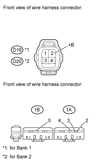 |
Disconnect the D19 or D20 A/F sensor connector.
Remove the integration relay from the engine room relay block.
Measure the resistance according to the value(s) in the table below.
| Tester Connection | Condition | Specified Condition |
| D19-2 (+B) - 1A-4 | Always | Below 1 Ω |
| D20-2 (+B) - 1A-4 | Always | Below 1 Ω |
| 1A-2 - 1B-5 | Always | Below 1 Ω |
| 1A-3 - Body ground | Always | Below 1 Ω |
| D19-2 (+B) or 1A-4 - Body ground | Always | 10 kΩ or higher |
| D20-2 (+B) or 1A-4 - Body ground | Always | 10 kΩ or higher |
| 1A-2 or 1B-5 - Body ground | Always | 10 kΩ or higher |
|
| ||||
| OK | ||
 | ||
| ||
| 5.CHECK HARNESS AND CONNECTOR (A/F SENSOR - ECM) |
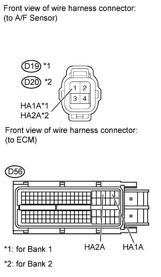 |
Disconnect the D19 or D20 A/F sensor connector.
Disconnect the D56 ECM connector.
Measure the resistance according to the value(s) in the table below.
| Tester Connection | Condition | Specified Condition |
| D19-1 (HA1A) - D56-22 (HA1A) | Always | Below 1 Ω |
| D20-1 (HA2A) - D56-20 (HA2A) | Always | Below 1 Ω |
| D19-1 (HA1A) or D56-22 (HA1A) - Body ground | Always | 10 kΩ or higher |
| D20-1 (HA2A) or D56-20 (HA2A) - Body ground | Always | 10 kΩ or higher |
|
| ||||
| OK | |
|
| 6.CHECK WHETHER DTC OUTPUT RECURS |
Connect the Techstream to the DLC3.
Turn the ignition switch to ON.
Turn the Techstream on.
Clear DTCs (Click here).
Start the engine.
Allow the engine to idle for 1 minute or more.
Enter the following menus: Powertrain / Engine and ECT / Trouble Codes.
Read DTCs.
| Result | Proceed to |
| No DTC is output | A |
| P0031, P0032, P0051, P0052, P101D or P103D is output | B |
|
| ||||
| A | ||
| ||
| ||

