 |
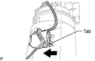
Slide the fuel sender gauge onto the fuel suction support to install it.
FUEL PUMP > INSTALLATION |
| 1. INSTALL FUEL SENDER GAUGE ASSEMBLY |
|
Slide the fuel sender gauge onto the fuel suction support to install it.
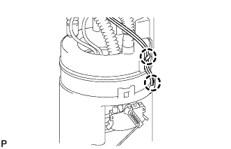 |
Attach the 2 claws to connect the wire harness.
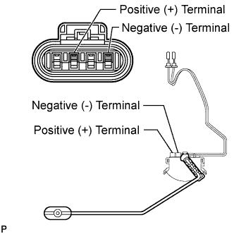 |
Insert the 2 wire terminals into the connector.
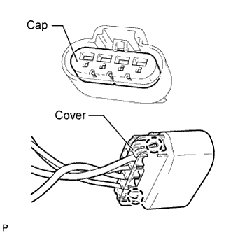 |
Attach the 2 claws to install the cover to the back end of the connector, and then install the cap.
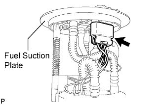 |
Connect the connector to the fuel suction plate.
| 2. INSTALL FUEL PRESSURE REGULATOR ASSEMBLY |
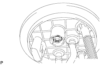 |
Apply a light coat of gasoline or spindle oil to the O-ring.
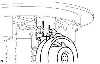 |
Attach the 2 claws to install the fuel pressure regulator.
| 3. INSTALL FUEL SUCTION WITH PUMP AND GAUGE TUBE ASSEMBLY |
Apply a light coat of gasoline or grease to a new gasket and install it to the fuel tank.
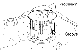 |
Align the protrusion of the fuel suction with pump and gauge tube assembly with the groove of the fuel tank.
Install the fuel suction with pump and gauge tube assembly into the fuel tank.
Put the retainer on the fuel tank. While holding the fuel suction with pump and gauge tube assembly, tighten the retainer one complete turn by hand.
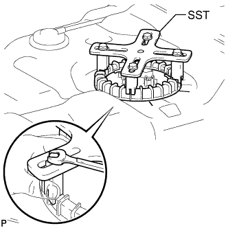 |
Set SST on the retainer.
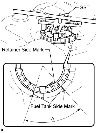 |
Using SST, tighten the retainer until the mark on the retainer is within range A on the fuel tank, as shown in the illustration.
| 4. INSTALL FUEL PRESSURE SWITCHING VALVE ASSEMBLY |
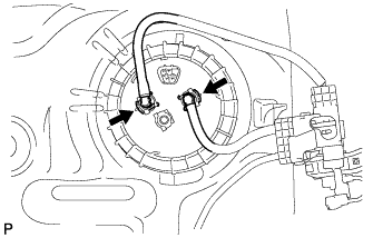 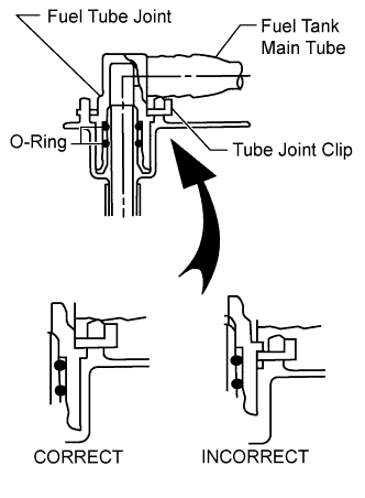 |
Install the fuel pressure switching valve assembly with the 2 tube joint clips.
| 5. INSTALL FUEL TANK ASSEMBLY |
Install the fuel tank assembly (Click here).