 |
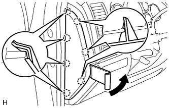
Using a moulding remover, detach the 7 claws and remove the side panel.
BRAKE BOOSTER > REMOVAL |
| 1. PRECAUTION |
| 2. DISCONNECT CABLE FROM NEGATIVE BATTERY TERMINAL |
| 3. DRAIN BRAKE FLUID |
| 4. REMOVE BRAKE MASTER CYLINDER SUB-ASSEMBLY |
Remove the brake master cylinder sub-assembly (Click here).
| 5. DISCONNECT VACUUM HOSE ASSEMBLY |
Slide the clip and disconnect the vacuum hose from the check valve.
| 6. DISCONNECT BRAKE BOOSTER CONNECTOR |
Disconnect the 2 brake booster connectors from the brake booster.
| 7. REMOVE FRONT DOOR SCUFF PLATE LH |
| 8. REMOVE COWL SIDE TRIM BOARD LH |
| 9. REMOVE INSTRUMENT SIDE PANEL LH |
|
Using a moulding remover, detach the 7 claws and remove the side panel.
| 10. REMOVE HOOD LOCK CONTROL LEVER SUB-ASSEMBLY |
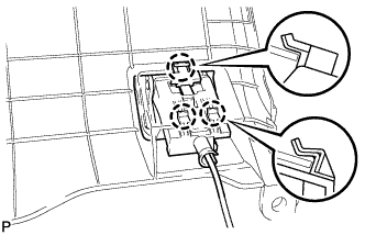 |
Disengage the 3 claws.
Disconnect the hood lock control cable and remove the hood lock control lever sub-assembly.
| 11. REMOVE LOWER INSTRUMENT PANEL FINISH PANEL SUB-ASSEMBLY LH |
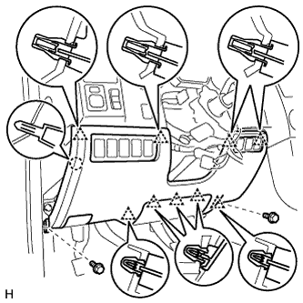 |
Remove the 2 bolts.
Detach the 9 clips and claw.
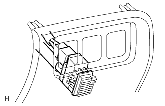 |
Detach the 2 claws and remove the sensor.
Remove the finish panel and then disconnect the connectors.
| 12. REMOVE LOWER NO. 1 INSTRUMENT PANEL AIR BAG ASSEMBLY |
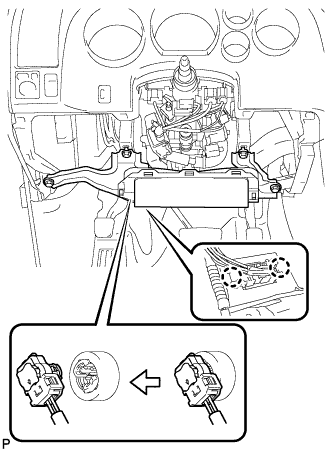 |
Remove the 4 bolts and remove the instrument panel airbag.
Detach the 2 claws and disconnect the DLC3.
Disconnect the connector.
| 13. REMOVE PUSH ROD PIN |
Remove the clip and push rod pin.
| 14. REMOVE BRAKE BOOSTER ASSEMBLY |
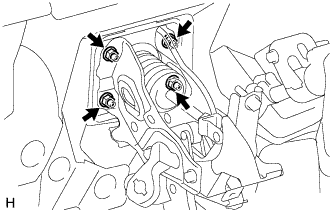 |
Remove the 4 nuts, and then pull out the brake booster.
Remove the brake booster gasket from the brake booster.
Loosen the lock nut and then remove the clevis.
| 15. REMOVE BRAKE VACUUM CHECK VALVE ASSEMBLY |