 |
Connect the connector.
- NOTICE:
- When handling the airbag connector, take care not to damage the airbag wire harness.
NETWORK GATEWAY ECU > INSTALLATION |
| 1. INSTALL NETWORK GATEWAY ECU |
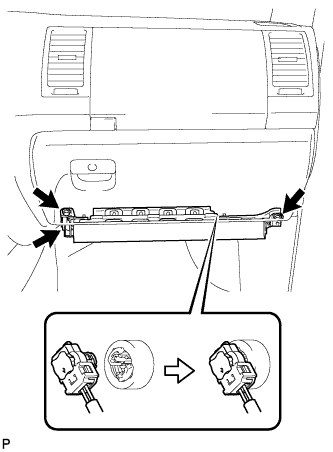
Install the network gateway ECU with the 2 nuts.
Connect the network gateway ECU connector.
| 2. INSTALL LOWER INSTRUMENT PANEL FINISH PANEL SUB-ASSEMBLY RH |
Connect the connector.
Attach the 3 claws to install the finish panel.
Install the 3 <D> screws and bolt <A>.
| 3. INSTALL LOWER NO. 2 INSTRUMENT PANEL AIRBAG ASSEMBLY |
|
Connect the connector.
Install the 3 bolts to install the instrument panel airbag.
| 4. INSTALL LOWER INSTRUMENT PANEL |
Attach the 2 claws.
Install the panel with the bolt <A> and screw <D>.
| 5. INSTALL NO. 2 INSTRUMENT PANEL UNDER COVER SUB-ASSEMBLY |
Attach the 2 guides and 4 claws.
Attach the clip to install the under cover.
| 6. INSTALL INSTRUMENT SIDE PANEL RH |
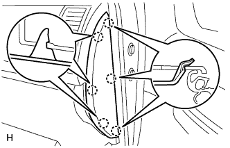 |
Attach the 6 claws to install the side panel.
| 7. INSTALL COWL SIDE TRIM BOARD RH |
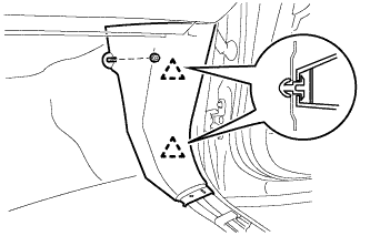 |
Engage the 2 clips to install the cowl side trim board.
Install the clip.
| 8. INSTALL FRONT DOOR SCUFF PLATE RH |
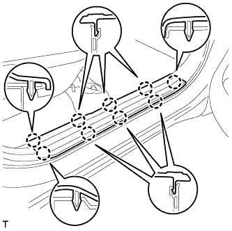 |
Engage the 9 claws to install the scuff plate.
| 9. CONNECT CABLE TO NEGATIVE BATTERY TERMINAL |
| 10. CHECK SRS WARNING LIGHT |