 |
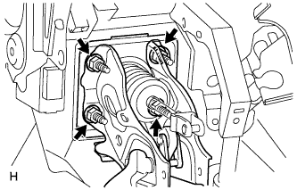
Install the brake pedal support with the 4 nuts.
- Torque:
- 15 N*m{ 155 kgf*cm , 11 ft.*lbf }
BRAKE PEDAL > INSTALLATION |
| 1. INSTALL BRAKE PEDAL PAD |
Install the brake pedal pad onto the brake pedal.
| 2. INSTALL BRAKE PEDAL SUPPORT SUB-ASSEMBLY |
|
Install the brake pedal support with the 4 nuts.
Install the No. 3 brake pedal bracket to the brake pedal support.
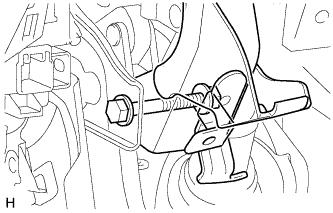 |
Temporarily install the brake pedal support, No. 3 brake pedal bracket and brake pedal lever with the bolt and nut.
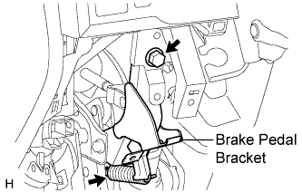 |
Install the bolt to the No. 3 brake pedal bracket.
Apply lithium soap base glycol grease to the inner surface of the hole on the brake pedal and return spring mounting bracket of the No. 3 brake pedal bracket.
Install the brake pedal return spring.
Tighten the bolt and nut.
| 3. INSTALL PUSH ROD PIN |
Apply a light coat of lithium soap base glycol grease to the inner surface of the hole on the brake pedal lever.
Set the push rod clevis in place, insert the push rod pin from outside the vehicle and then install a new clip.
| 4. INSTALL STOP LIGHT SWITCH MOUNTING ADJUSTER |
Install the stop light switch mounting adjuster.
| 5. INSTALL STOP LIGHT SWITCH ASSEMBLY |
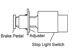 |
Install the stop light switch into the adjuster until it slightly touches the brake pedal.
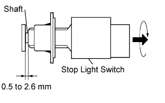 |
Make a quarter turn clockwise to install the stop light switch.
Check the stop light switch clearance.
Connect the stop light switch connector to the stop light switch.
| 6. INSTALL NO. 1 SIDE DEFROSTER NOZZLE DUCT |
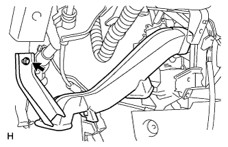 |
Install the defroster nozzle duct with the bolt.
| 7. INSTALL LOWER NO. 1 INSTRUMENT PANEL AIR BAG ASSEMBLY |
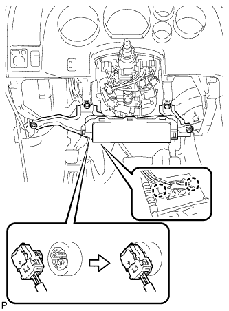 |
Connect the connector.
Attach the 2 claws to install the DLC3.
Install the 4 bolts to install the instrument panel airbag.
| 8. INSTALL LOWER INSTRUMENT PANEL FINISH PANEL SUB-ASSEMBLY LH |
Attach the 2 claws to install the sensor.
Connect the connectors.
Attach the 9 clips and claw to install the finish panel.
Install the 2 <A> bolts.
| 9. INSTALL HOOD LOCK CONTROL LEVER SUB-ASSEMBLY |
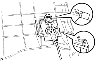 |
Connect the hood lock control cable assembly to the hood lock control lever sub-assembly.
engage the 3 claws to install the hood lock lever
| 10. INSTALL INSTRUMENT SIDE PANEL LH |
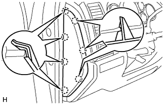 |
Attach the 7 claws to install the side panel.
| 11. INSTALL COWL SIDE TRIM BOARD LH |
| 12. INSTALL FRONT DOOR SCUFF PLATE LH |
| 13. CONNECT CABLE TO NEGATIVE BATTERY TERMINAL |
| 14. CHECK AND ADJUST BRAKE PEDAL |
Check and adjust brake pedal (Click here).
| 15. CHECK MASTER CYLINDER PRESSURE SENSOR SIGNAL |
Check the master cylinder pressure sensor signal (Click here).