 |
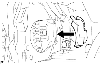
Install the flywheel housing side cover.
STARTER > INSTALLATION |
| 1. INSTALL STARTER ASSEMBLY |
|
Install the flywheel housing side cover.
Install the starter with the 2 bolts.
Install the starter wire with the nut.
Connect the starter connector.
Attach the 2 wire harness clamps.
| 2. INSTALL STARTER COVER |
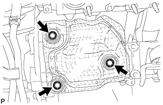 |
Install the starter cover with the 3 bolts.
| 3. INSTALL EXHAUST MANIFOLD SUB-ASSEMBLY RH |
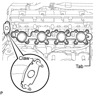 |
Install a new gasket to the cylinder head and a new gasket to the No. 2 air tube.
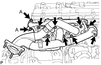 |
Temporarily install the exhaust manifold with the 2 nuts labeled A and 8 new nuts.
Uniformly tighten the nuts that are not labeled A, and then tighten the 2 nuts labeled A.
| 4. INSTALL NO. 1 EXHAUST MANIFOLD HEAT INSULATOR |
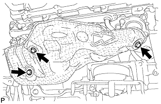 |
Install the No. 1 exhaust manifold heat insulator with the 3 bolts.
| 5. INSTALL FRONT NO. 3 FLOOR HEAT INSULATOR |
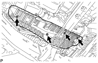 |
Install the front No. 3 floor heat insulator with the 4 bolts.
| 6. INSTALL FRONT EXHAUST PIPE ASSEMBLY |
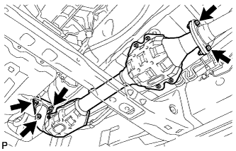 |
Install a new gasket and the front exhaust pipe assembly to the exhaust manifold RH with 3 new nuts.
Install a new gasket and the front exhaust pipe assembly to the center exhaust pipe assembly with the 2 bolts.
Connect the air fuel ratio sensor connector.
Connect the heated oxygen sensor connector and 2 clamps.
| 7. INSTALL ENGINE OIL LEVEL DIPSTICK GUIDE |
Apply a light coat of engine oil to a new O-ring.
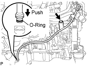 |
Install the O-ring to the guide.
Install the dipstick guide with the bolt.
Connect the wire harness clamp.
Install the dipstick.
| 8. INSTALL FRONT FENDER APRON SEAL RH |
Install the fender apron seal with the 6 clips.
| 9. INSPECT FOR EXHAUST GAS LEAK |
| 10. INSTALL NO. 1 ENGINE UNDER COVER |
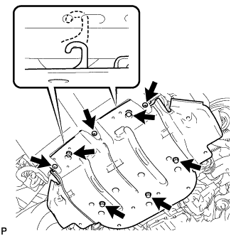 |
Hook the engine under cover to the vehicle body as shown in the illustration.
Install the 3 screws and 5 bolts.
| 11. CONNECT CABLE TO NEGATIVE BATTERY TERMINAL |