FRONT AIR CONDITIONING UNIT > INSTALLATION |
| 1. INSTALL FRONT AIR CONDITIONING UNIT |
|
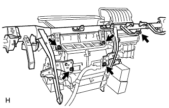
Temporarily tighten the air conditioning unit with the 3 bolts and 2 screws.
| 2. INSTALL INSTRUMENT PANEL REINFORCEMENT ASSEMBLY |
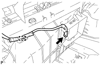 |
Connect the connector and clamp and install the wire harness.
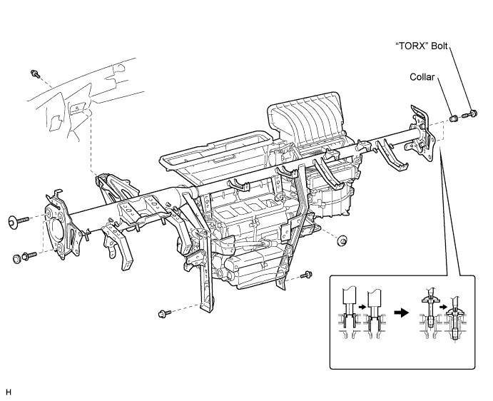
Install the instrument panel reinforcement.
for Passenger Side:
Using a 12 mm hexagon wrench, install the 2 collars.
for Passenger Side:
Using a T40 "TORX" socket, install the 2 "TORX" bolts.
for Driver Side:
Install the 3 bolts and 2 caps.
Install the instrument panel reinforcement with the 3 bolts and nut.
|
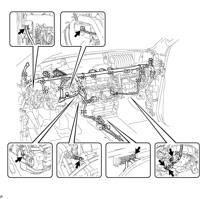
Tighten the air conditioning unit with the 3 bolts and 2 screws.
Connect the connectors and clamps and install the wire harness.
Install the ground wire with the bolt.
| 3. INSTALL NO. 1 ECU INTEGRATION BRACKET |
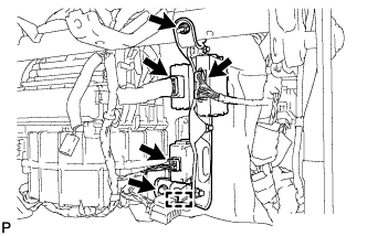 |
Install the ECU integration bracket with the bolt and nut.
Connect the connectors and clamp.
| 4. INSTALL TURN SIGNAL FLASHER ASSEMBLY |
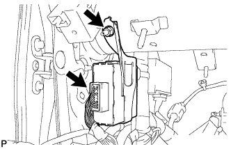 |
Install the turn signal flasher with the nut.
Connect the connector.
| 5. INSTALL MAIN BODY ECU |
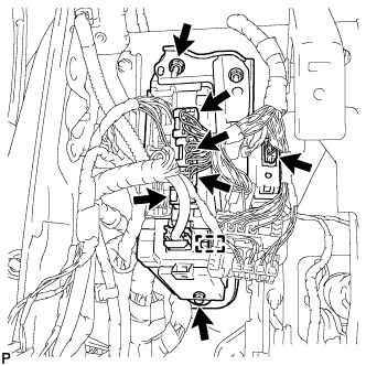 |
Install the main body ECU with the bolt and nut.
Connect the connectors and clamp.
| 6. INSTALL REAR NO. 2 AIR DUCT |
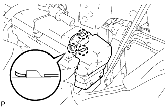 |
Attach the 3 claws and install the air duct.
| 7. INSTALL REAR NO. 1 AIR DUCT |
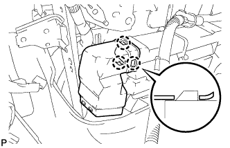 |
Attach the 3 claws and install the air duct.
| 8. INSTALL TRANSMISSION FLOOR SHIFT ASSEMBLY |
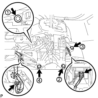 |
Install the transmission floor shift with the 4 bolts. Tighten the bolts in the order shown in the illustration.
Connect the clamp and 2 connectors.
| 9. CONNECT TRANSMISSION CONTROL CABLE ASSEMBLY |
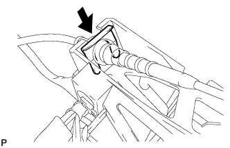 |
Install the cable outer of the transmission control cable to the shift lever retainer, and install a new clip.
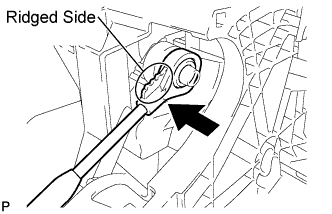 |
Connect the transmission control cable end to the shift lever.
| 10. INSTALL INSTRUMENT PANEL SUB-ASSEMBLY (for 8 Speakers) |
Attach the 5 claws to install the instrument panel.
Install the 3 <C> bolts and 2 <E> nuts.
Install the 2 <F> passenger airbag bolts.
Connect the connectors and attach the wire harness clamps.
Install the wire harness with the bolt.
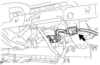 |
Connect the airbag connector.
| 11. INSTALL INSTRUMENT PANEL SUB-ASSEMBLY (for 14 Speakers) |
Attach the 5 claws to install the instrument panel.
Install the 3 <C> bolts and 2 <E> nuts.
Install the 2 <F> passenger airbag bolts.
Connect the connectors and attach the wire harness clamps.
Install the wire harness with the bolt.
|
Connect the airbag connector.
| 12. INSTALL STEERING COLUMN ASSEMBLY (for Manual Tilt and Manual Telescopic Steering Column) |
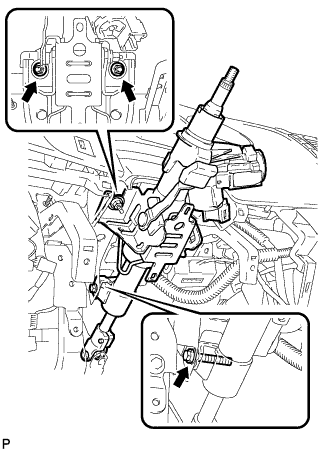 |
Install the steering column with the bolt and 2 nuts.
Connect the connectors and wire harness clamps.
| 13. INSTALL STEERING COLUMN ASSEMBLY (for Power Tilt and Power Telescopic Steering Column) |
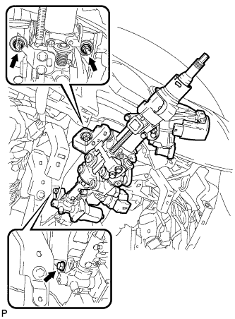 |
Install the steering column with the bolt and 2 nuts.
Connect the connectors and wire harness clamps.
| 14. INSTALL STEERING INTERMEDIATE SHAFT ASSEMBLY |
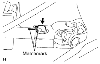 |
Align the matchmarks on the steering column and install the steering intermediate shaft.
Install the bolt.
| 15. INSTALL NO. 3 AIR DUCT SUB-ASSEMBLY |
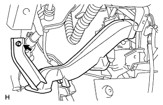 |
Install the air duct with the bolt.
| 16. INSTALL REAR NO. 4 AIR DUCT |
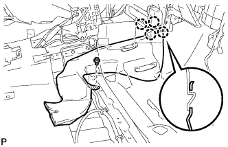 |
Attach the 4 claws and install the air duct.
Install the clip.
| 17. INSTALL REAR NO. 3 AIR DUCT |
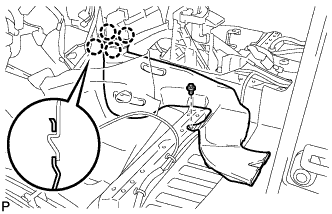 |
Attach the 4 claws and install the air duct.
Install the clip.
| 18. INSTALL STEREO COMPONENT AMPLIFIER ASSEMBLY (for 14 Speakers) |
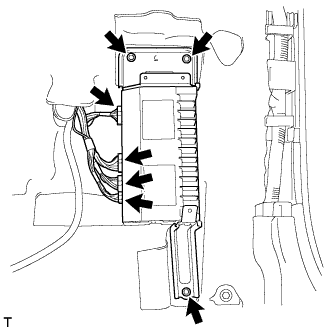 |
Install the amplifier with the 3 bolts.
Connect the 4 connectors.
| 19. INSTALL AUDIO AMPLIFIER COVER (for 14 Speakers) |
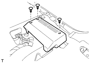 |
Set the cover on the stereo amplifier assembly.
Engage the 3 clips.
| 20. INSTALL FRONT RH SEAT ASSEMBLY (for RH Side) |
Place the front seat assembly in the cabin.
Connect the seat wire connectors under the seat.
Connect the cable to the negative (-) battery terminal.
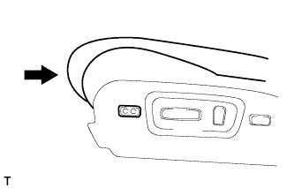 |
Operate the leg support adjustment switch to move the seat cushion to the closed position.
Operate the power seat switch to move the seat to the rearmost position.
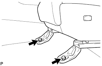 |
Install the 2 bolts.
Operate the power seat switch to move the seat to the foremost position.
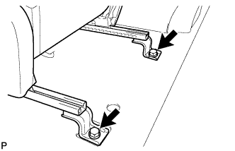 |
Install the 2 bolts.
| 21. INSTALL SEAT TRACK OUTER COVER RH (for RH Side) |
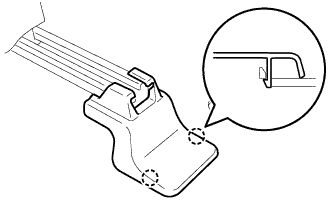 |
Attach the 2 claws to install the seat track cover.
| 22. INSTALL SEAT TRACK INNER COVER RH (for RH Side) |
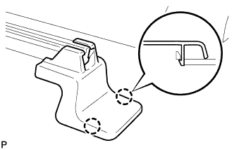 |
Attach the 2 claws to install the seat track cover.
| 23. INSTALL FRONT SEAT HEADREST ASSEMBLY (for RH Side) |
| 24. INSTALL FRONT LH SEAT ASSEMBLY (for LH Side) |
Install the front seat.
Connect the seat wire connectors under the seat.
Operate the seat track adjusting handle to move the seat to the rearmost position.
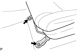 |
Install the 2 bolts.
Operate the seat track adjusting handle to move the seat to the foremost position.
|
Install the 2 bolts.
| 25. INSTALL SEAT TRACK OUTER COVER LH (for LH Side) |
|
Engage the 2 claws to install the seat track cover.
| 26. INSTALL SEAT TRACK INNER COVER LH (for LH Side) |
|
Engage the 2 claws to install the seat track cover.
| 27. INSTALL FRONT SEAT HEADREST ASSEMBLY (for LH Side) |
| 28. INSTALL FRONT NO. 4 SPEAKER ASSEMBLY (for 14 Speakers) |
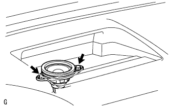 |
Connect the connector.
Temporarily install the speaker by aligning the positioning pins of the speaker with the instrument panel.
Install the speaker with the 2 bolts.
| 29. INSTALL NO. 3 INSTRUMENT PANEL SPEAKER PANEL SUB-ASSEMBLY |
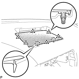 |
Attach the 6 clips and 2 claws to install the speaker panel.
| 30. INSTALL FRONT NO. 2 SPEAKER ASSEMBLY RH |
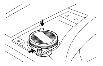 |
Connect the speaker connector.
Temporarily install the speaker by aligning the positioning pins of the speaker with the instrument panel.
Install the speaker with the 2 bolts.
| 31. INSTALL NO. 2 INSTRUMENT PANEL SPEAKER PANEL SUB-ASSEMBLY |
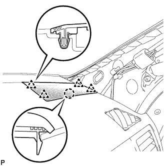 |
Attach the 4 clips and claw to install the speaker panel.
| 32. INSTALL FRONT NO. 2 SPEAKER ASSEMBLY LH |
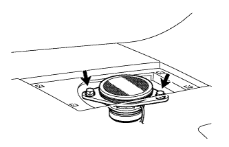 |
Connect the speaker connector.
Temporarily install the speaker by aligning the positioning pins of the speaker with the instrument panel.
Install the speaker with the 2 bolts.
| 33. INSTALL INSTRUMENT PANEL SPEAKER PANEL SUB-ASSEMBLY |
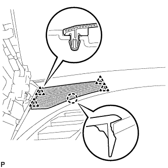 |
Attach the 4 clips and claw to install the speaker panel.
| 34. INSTALL NO. 2 INSTRUMENT PANEL BOX DOOR SUB-ASSEMBLY |
Attach the clip to install the box door.
Install the 6 <B> or <H> screws.
| 35. INSTALL LOWER INSTRUMENT PANEL FINISH PANEL SUB-ASSEMBLY RH |
Connect the connector.
Attach the 3 claws to install the finish panel.
Install the 3 <D> screws and bolt <A>.
| 36. INSTALL LOWER NO. 2 INSTRUMENT PANEL AIRBAG ASSEMBLY |
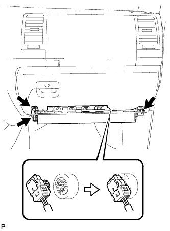 |
Connect the connector.
Install the 3 bolts to install the instrument panel airbag.
| 37. INSTALL LOWER INSTRUMENT PANEL |
Attach the 2 claws.
Install the panel with the bolt <A> and screw <D>.
| 38. INSTALL NO. 2 INSTRUMENT PANEL UNDER COVER SUB-ASSEMBLY |
Attach the 2 guides and 4 claws.
Attach the clip to install the under cover.
| 39. INSTALL FRONT PILLAR GARNISH RH |
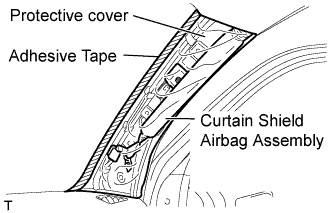 |
Remove the protective cover.
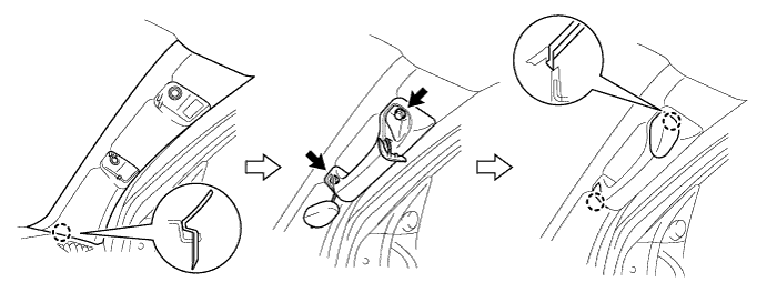
Engage the claw to install the front pillar garnish.
Install the assist grip with the 2 bolts.
Engage the 2 claws to install the 2 assist grip plugs.
| 40. INSTALL FRONT DOOR OPENING TRIM WEATHERSTRIP RH |
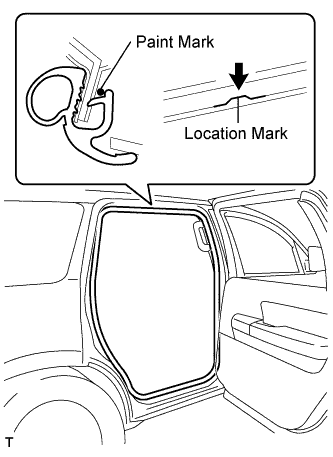 |
Align the location mark with the paint mark first, and install the rear door opening trim weatherstrip, as shown in the illustration.
| Area | Color |
| RH side | Pink |
| LH side | Purple |
| 41. INSTALL COWL SIDE TRIM BOARD RH |
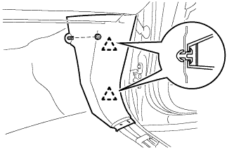 |
Engage the 2 clips to install the cowl side trim board.
Install the clip.
| 42. INSTALL FRONT DOOR SCUFF PLATE RH |
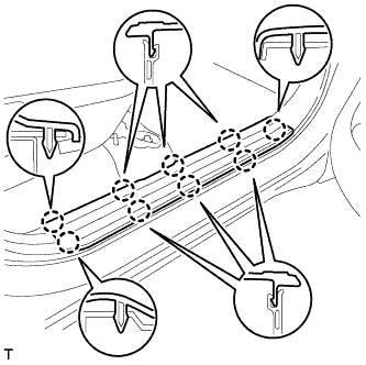 |
Engage the 9 claws to install the scuff plate.
| 43. INSTALL INSTRUMENT SIDE PANEL RH |
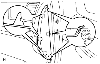 |
Attach the 6 claws to install the side panel.
| 44. INSTALL NAVIGATION RECEIVER ASSEMBLY WITH BRACKET (w/ Navigation System) |
for DVD:
Install the navigation receiver assembly with bracket .
for SD:
Install the navigation receiver assembly with bracket .
| 45. INSTALL RADIO RECEIVER ASSEMBLY WITH BRACKET (w/ Radio Receiver) |
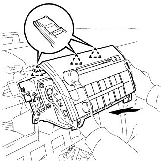 |
Connect the connectors.
Insert the radio receiver and engage the 3 clips on its backside.
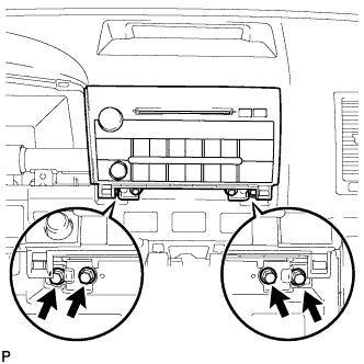 |
Install the radio receiver with the 4 bolts.
| 46. INSTALL INTEGRATION CONTROL AND PANEL ASSEMBLY |
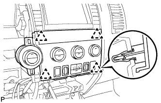 |
Connect the connectors.
Attach the 4 clips and install the panel.
| 47. INSTALL CENTER LOWER INSTRUMENT PANEL FINISH PANEL |
Connect the connectors.
Attach the 4 clips and 2 claws to install the finish panel.
| 48. INSTALL COMBINATION METER ASSEMBLY |
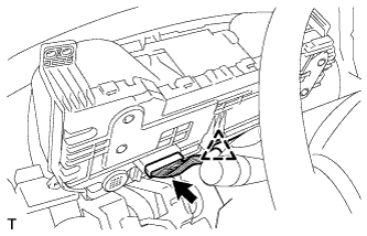 |
Connect the connector and engage the clip and install the combination meter assembly.
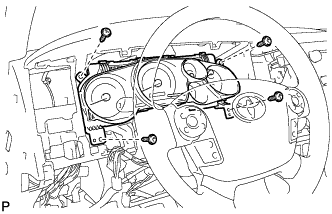 |
Install the 4 screws.
| 49. INSTALL INSTRUMENT CLUSTER FINISH PANEL ASSEMBLY |
Attach the 12 clips to install the finish panel.
Connect the 2 connectors and attach the wire harness clamp.
Attach the 4 claws to install the instrument panel finish panel retainer.
| 50. INSTALL FRONT CONSOLE BOX |
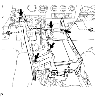 |
Install the front console box with the 5 screws and 2 clips.
Attach the 2 clamps.
| 51. INSTALL REAR CONSOLE BOX ASSEMBLY |
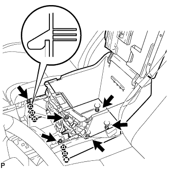 |
Attach the 6 claws to install the rear console box.
Install the 2 screws and 4 bolts.
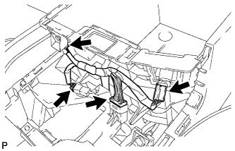 |
Connect the connectors.
| 52. INSTALL CONSOLE BOX CARPET |
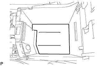 |
Install the console box carpet.
| 53. INSTALL REAR CONSOLE BOX POCKET |
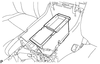 |
Install the rear console box pocket.
| 54. INSTALL REAR UPPER CONSOLE PANEL SUB-ASSEMBLY |
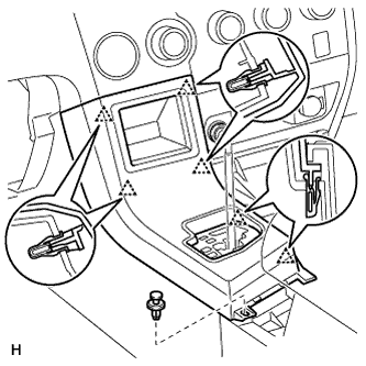 |
Connect the connectors.
Attach the 6 clips to install the console panel.
Install the clip.
| 55. INSTALL UPPER CONSOLE PANEL SUB-ASSEMBLY |
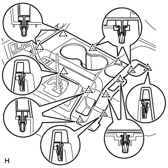 |
Attach the 12 clips to install the console panel.
| 56. INSTALL SHIFT LEVER KNOB SUB-ASSEMBLY |
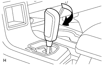 |
Install the shift lever knob and twist it in the direction indicated by the arrow.
| 57. INSTALL LOWER INSTRUMENT PANEL FINISH PANEL SUB-ASSEMBLY LH |
Attach the 2 claws to install the sensor.
Connect the connectors.
Attach the 9 clips and claw to install the finish panel.
Install the 2 <A> bolts.
| 58. INSTALL HOOD LOCK CONTROL LEVER SUB-ASSEMBLY |
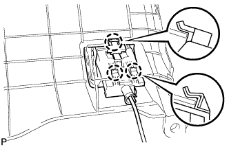 |
Connect the hood lock control cable assembly to the hood lock control lever sub-assembly.
engage the 3 claws to install the hood lock lever
| 59. INSTALL INSTRUMENT SIDE PANEL LH |
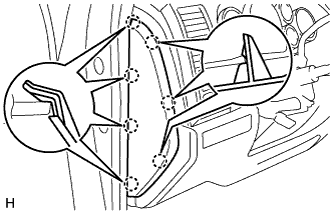 |
Attach the 7 claws to install the side panel.
| 60. INSTALL FRONT PILLAR GARNISH LH |
| 61. INSTALL FRONT DOOR OPENING TRIM WEATHERSTRIP LH |
| 62. INSTALL COWL SIDE TRIM BOARD LH |
| 63. INSTALL FRONT DOOR SCUFF PLATE LH |
| 64. INSTALL TURN SIGNAL SWITCH ASSEMBLY WITH SPIRAL CABLE SUB-ASSEMBLY |
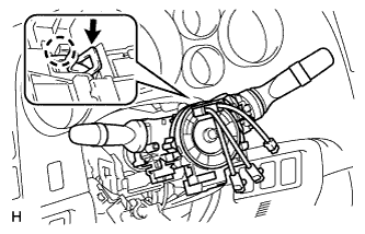 |
Using pliers, grip the claws of the clamp and install the combination switch with spiral cable to the steering column assembly with the clamp.
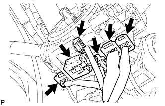 |
Connect the 6 connectors to the combination switch with spiral cable.
| 65. INSTALL UPPER STEERING COLUMN COVER |
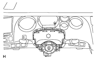 |
Attach the claw to install the upper steering column cover.
Attach the 4 clips.
| 66. INSTALL LOWER STEERING COLUMN COVER |
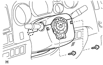 |
Attach the 2 claws to install the lower steering column cover.
Install the 2 screws.
| 67. INSTALL STEERING WHEEL ASSEMBLY |
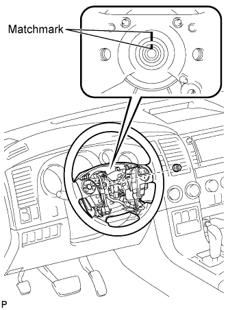 |
Align the matchmarks on the steering wheel and steering main shaft.
Install the steering wheel set nut.
| 68. INSTALL STEERING PAD |
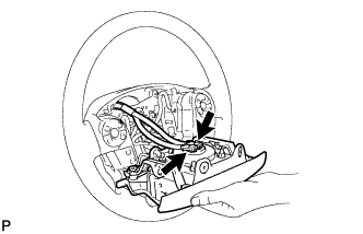 |
Confirm that the ignition switch is turned off.
Confirm that the negative battery terminal is disconnected.
Connect the horn terminal.
Connect the airbag connector.
Install the steering pad.
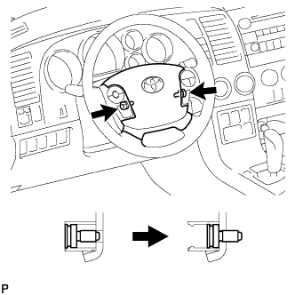 |
Using "TORX" socked wrench T30, tighten the 2 screws.
| 69. INSTALL LOWER NO. 3 STEERING WHEEL COVER |
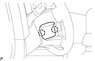 |
Attach the 2 claws to install the cover.
| 70. INSTALL LOWER NO. 2 STEERING WHEEL COVER |
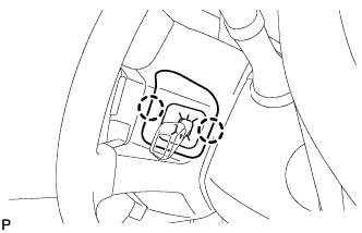 |
Attach the 2 claws to install the cover.
| 71. INSTALL FRONT WIPER MOTOR AND LINK ASSEMBLY |
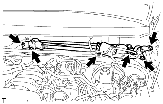 |
Install the wiper motor and link assembly with the 4 bolts and nut.
Connect the connector.
| 72. INSTALL COWL TOP VENTILATOR LOUVER SUB-ASSEMBLY |
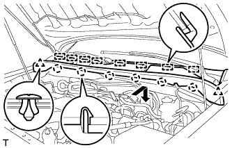 |
Engage the 6 claws and 8 guides and install the cowl top ventilator louver sub-assembly.
Install the 2 clips.
| 73. INSTALL FRONT FENDER TO COWL SIDE SEAL LH |
| 74. INSTALL FRONT FENDER TO COWL SIDE SEAL RH |
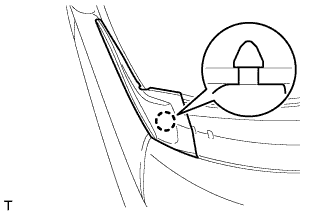 |
Engage the claw and install the front fender to cowl side seal.
| 75. INSTALL FRONT WIPER ARM AND BLADE ASSEMBLY LH |
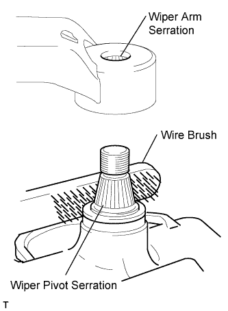 |
Clean any metal powder off the serrated part of the wiper arm with a round wire brush or the equivalent (when reinstalling).
Clean the wiper pivot serrations with a wire brush.
Operate the wiper, and then stop the wiper motor in the automatic stop position.
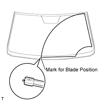 |
Align the blade tip with the mark on the glass, as shown in the illustration.
Tighten the nut on the front wiper arm and blade.
Operate the front wipers while spraying washer fluid on the windshield glass. Make sure that the front wipers function properly and there is no interference with the vehicle body.
| 76. INSTALL FRONT WIPER ARM AND BLADE ASSEMBLY RH |
|
Clean any metal powder off the serrated part of the wiper arm with a round wire brush or the equivalent (when reinstalling).
Clean the wiper pivot serrations with a wire brush.
Operate the wiper, and then stop the wiper motor in the automatic stop position.
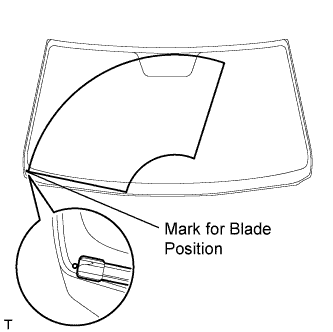 |
Align the blade tip with the mark on the glass, as shown in the illustration.
Tighten the nut on the front wiper arm and blade.
| 77. CONNECT HEATER WATER OUTLET HOSE A |
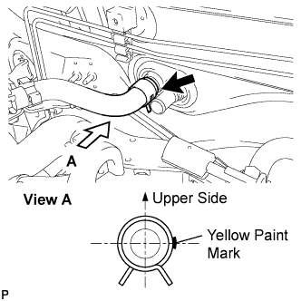 |
Connect the water hose onto the air conditioning unit.
| 78. CONNECT HEATER WATER INLET HOSE A |
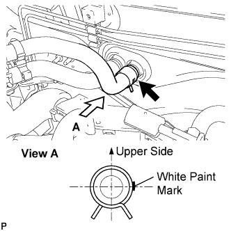 |
Connect the water hose onto the air conditioning unit.
| 79. CONNECT COOLER REFRIGERANT LIQUID PIPE B |
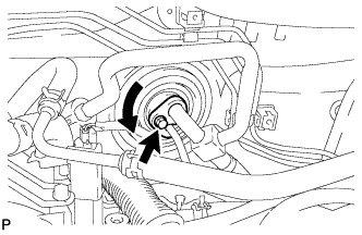 |
Remove the attached vinyl tape from the pipe.
Sufficiently apply compressor oil to a new O-ring and the fitting surface of the suction pipe.
Install the 2 O-rings on the suction pipe and liquid pipe.
Move the hook connector in the direction indicated by the arrow in the illustration.
Insert the pipe joint into the fitting hole securely and tighten the bolt.
| 80. INSPECT SHIFT LEVER POSITION |
When moving the shift lever from P to R with the ignition switch ON and the brake pedal depressed, make sure that it moves smoothly and correctly into position.
Check that the shift lever does not stop when moving the shift lever from R to P, and check that the shift lever does not stick when moving the shift lever from D to S.
Start the engine and make sure that the vehicle moves forward after moving the shift lever from N to D and moves rearward after moving the shift lever to R.
If the operation cannot be done as specified, inspect the park/neutral position switch assembly and check the shift lever assembly installation condition.
| 81. ADJUST SHIFT LEVER POSITION |
Move the shift lever to the N position.
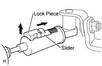 |
Fold back the transmission control cable adjust case cover. Then while sliding the slider toward the cable end side, press the lock piece from the back side to release the lock.
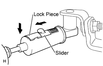 |
Check that the adjust case's spring is applying enough tension to the shift control cable. Then press the lock piece to set the lock.
Return the cover of the adjust case to its original position.
Inspect the operation after the adjustment.
| 82. CONNECT CABLE TO NEGATIVE BATTERY TERMINAL |
| 83. ADD ENGINE COOLANT (for 1UR-FE) |
Add engine coolant.
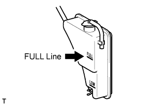 |
Slowly pour coolant into the radiator reservoir until it reaches the FULL line.
Install the reservoir cap.
Press the inlet and outlet radiator hoses several times by hand, and then check the coolant level. If the coolant level is low, add coolant.
Install the radiator cap.
Start the engine and warm it up until the thermostat opens.
Maintain the engine speed at 2000 to 2500 rpm.
Press the inlet and outlet radiator hoses several times by hand to bleed air.
Stop the engine, and wait until the engine coolant cools down to ambient temperature.
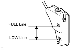 |
Check that the coolant level is between the FULL and LOW lines.
If the coolant level is below the LOW line, repeat all of the procedures above.
If the coolant level is above the FULL line, drain coolant so that the coolant level is between the FULL and LOW lines.
| 84. ADD ENGINE COOLANT (for 3UR-FE) |
Add engine coolant.
| Item | Specified Condition |
| w/ Trailer Towing System | 14.6 liters (15.4 US qts., 12.8 Imp. qts.) |
| w/o Trailer Towing System | 13.7 liters (14.5 US qts., 12.0 Imp. qts.) |
|
Slowly pour coolant into the radiator reservoir until it reaches the FULL line.
Install the reservoir cap.
Press the inlet and outlet radiator hoses several times by hand, and then check the coolant level. If the coolant level is low, add coolant.
Install the radiator cap.
Start the engine and warm it up until the thermostat opens.
Maintain the engine speed at 2000 to 2500 rpm.
Press the inlet and outlet radiator hoses several times by hand to bleed air.
Stop the engine, and wait until the engine coolant cools down to ambient temperature.
|
Check that the coolant level is between the FULL and LOW lines.
If the coolant level is below the LOW line, repeat all of the procedures above.
If the coolant level is above the FULL line, drain coolant so that the coolant level is between the FULL and LOW lines.
| 85. ADD ENGINE COOLANT (for 3UR-FBE) |
Add engine coolant.
| Item | Specified Condition |
| w/ Trailer Towing System | 14.6 liters (15.4 US qts., 12.8 Imp. qts.) |
| w/o Trailer Towing System | 13.7 liters (14.5 US qts., 12.0 Imp. qts.) |
|
Slowly pour coolant into the radiator reservoir until it reaches the FULL line.
Install the reservoir cap.
Press the inlet and outlet radiator hoses several times by hand, and then check the coolant level. If the coolant level is low, add coolant.
Install the radiator cap.
Start the engine and warm it up until the thermostat opens.
Maintain the engine speed at 2000 to 2500 rpm.
Press the inlet and outlet radiator hoses several times by hand to bleed air.
Stop the engine, and wait until the engine coolant cools down to ambient temperature.
|
Check that the coolant level is between the FULL and LOW lines.
If the coolant level is below the LOW line, repeat all of the procedures above.
If the coolant level is above the FULL line, drain coolant so that the coolant level is between the FULL and LOW lines.
| 86. INSPECT FOR COOLANT LEAK (for 1UR-FE) |
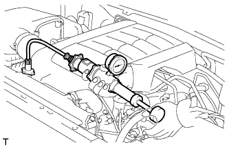 |
Fill the radiator with coolant and attach a radiator cap tester.
Warm up the engine.
Using the radiator cap tester, increase the pressure inside the radiator to 118 kPa (1.2 kgf/cm2, 17 psi), and check that the pressure does not drop.
If the pressure drops, check the hoses, radiator and water pump for leaks. If no external leaks are found, check the heater core, cylinder block and head.
| 87. INSPECT FOR COOLANT LEAK (for 3UR-FE) |
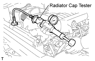 |
Fill the radiator with coolant and attach a radiator cap tester.
Warm up the engine.
Using the radiator cap tester, increase the pressure inside the radiator to 118 kPa (1.2 kgf/cm2, 17 psi), and check that the pressure does not drop.
If the pressure drops, check the hoses, radiator and water pump for leaks. If no external leaks are found, check the heater core, cylinder block and head.
| 88. INSPECT FOR COOLANT LEAK (for 3UR-FBE) |
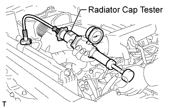 |
Fill the radiator with coolant and attach a radiator cap tester.
Warm up the engine.
Using the radiator cap tester, increase the pressure inside the radiator to 118 kPa (1.2 kgf/cm2, 17 psi), and check that the pressure does not drop.
If the pressure drops, check the hoses, radiator and water pump for leaks. If no external leaks are found, check the heater core, cylinder block and head.
| 89. CHARGE REFRIGERANT |
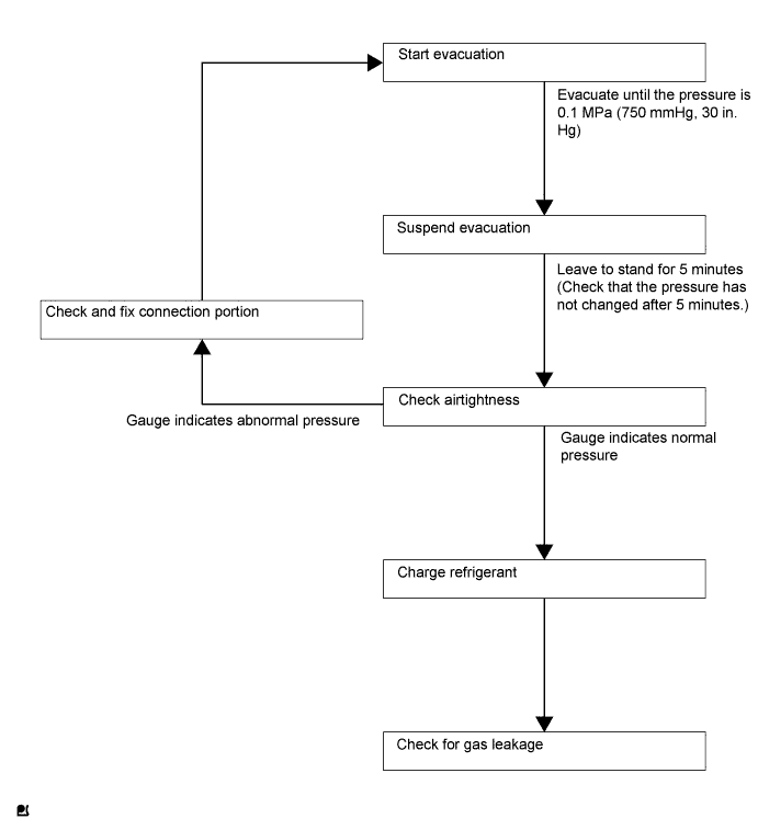
Perform vacuum purging using a vacuum pump.
Charge refrigerant HFC-134a (R134a).
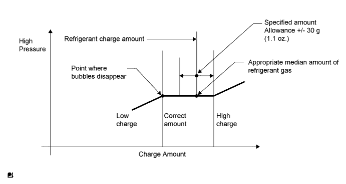
Install the caps onto the service valves on the refrigerant line.
| 90. WARM UP ENGINE |
| 91. INSPECT FOR REFRIGERANT LEAK |
After recharging the refrigerant gas, check for refrigerant gas leakage using a halogen leak detector.
Perform the operation as follows:
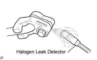 |
Using the halogen leak detector, check the refrigerant line, especially at the connection points, for leakage.
If no gas leakage is detected from the drain hose, remove the blower motor from the cooling unit. Insert the halogen leak detector sensor into the unit and perform the test.
Disconnect the pressure switch connector and leave it for approximately 20 minutes. Bring the halogen leak detector close to the pressure switch and perform the test.
| 92. INSTALL NO. 1 ENGINE UNDER COVER |
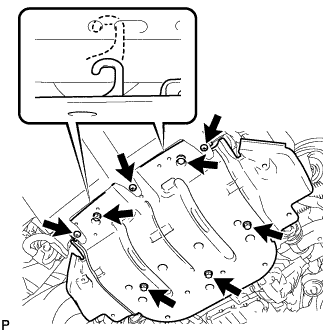 |
Hook the engine under cover to the vehicle body as shown in the illustration.
Install the 3 screws and 5 bolts.
| 93. CHECK SRS WARNING LIGHT |
Check the SRS warning light (Click here).