 |
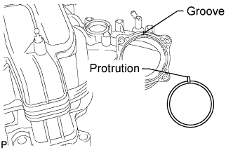
Align the protrusion of a new gasket with the groove of the intake manifold, and install the gasket.
INTAKE MANIFOLD > INSTALLATION |
| 1. INSTALL THROTTLE BODY ASSEMBLY |
|
Align the protrusion of a new gasket with the groove of the intake manifold, and install the gasket.
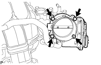 |
Install the throttle body with the 4 bolts.
| 2. INSTALL MANIFOLD ABSOLUTE PRESSURE SENSOR |
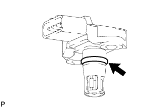 |
Install a new O-ring to the manifold absolute pressure sensor.
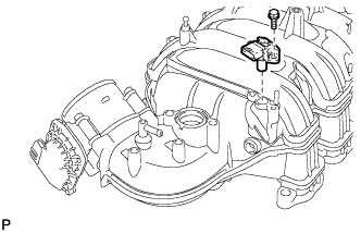 |
Install the manifold absolute pressure sensor with the screw.
Connect the manifold absolute pressure sensor connector.
| 3. INSTALL UNION TO CONNECTOR TUBE HOSE ASSEMBLY |
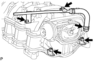 |
Install the union to connector tube hose to the intake manifold.
Install the 2 bolts and attach the hose clamp.
Install the 2 wire harness brackets with the 2 bolts.
| 4. INSTALL PURGE VSV |
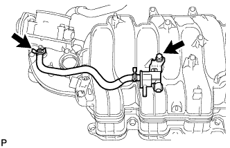 |
Connect the purge line hose to the intake manifold.
Install the purge VSV to the intake manifold with the bolt.
| 5. INSTALL VACUUM SWITCHING VALVE ASSEMBLY (for ACIS) |
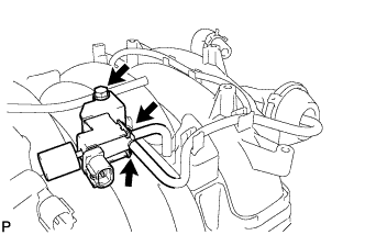 |
Install the vacuum switching valve to the intake manifold with the bolt.
Connect the 2 vacuum hoses to the vacuum switching valve.
| 6. INSTALL STUD BOLT |
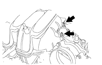 |
Using an E5 "TORX" socket wrench, install the 2 stud bolts.
| 7. INSTALL V-BANK COVER PIN |
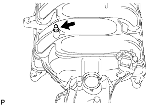 |
Install the pin to the intake manifold.
| 8. INSTALL V-BANK COVER BRACKET |
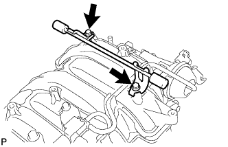 |
Install the bracket with the 2 bolts.
| 9. INSTALL FUEL TUBE SUB-ASSEMBLY |
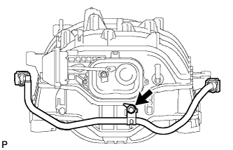 |
Install the fuel tube to the intake manifold with the bolt.
| 10. INSTALL INTAKE MANIFOLD |
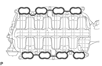 |
Place 2 new gaskets on the intake manifold.
Place the intake manifold on the cylinder head.
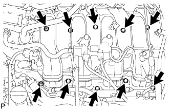 |
Install and uniformly tighten the 8 bolts and 2 nuts in several steps.
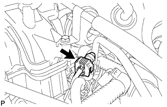 |
Connect the fuel tube to the fuel delivery pipe LH (Click here).
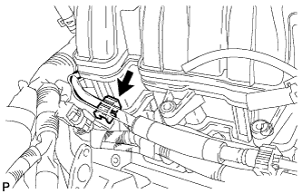 |
Connect the fuel tube to the fuel delivery pipe RH (Click here).
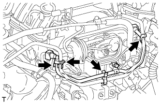 |
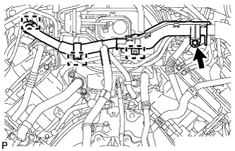
Attach the 4 clamps to the fuel tube as shown in the illustration.
 |
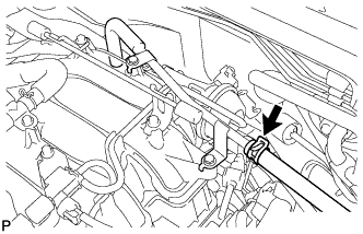
Attach the 3 wire harness clamps to the 3 wire harness brackets.
Connect the wire harness to the wire harness bracket with the bolt.
 |
Connect the vacuum hose.
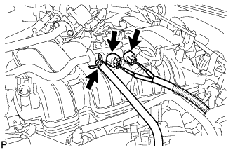 |
Connect the purge VSV connector.
Connect the purge line hose to the purge VSV.
Connect the vacuum switching valve connector (for ACIS).
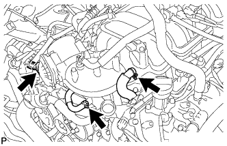 |
Connect the No. 1 ventilation hose.
Connect the No. 4 water by-pass hose.
Connect the throttle body connector.
| 11. INSTALL VENTILATION HOSE ASSEMBLY |
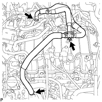 |
Install the ventilation hose with the bolt.
Connect the ventilation hose to the ventilation pipe of the cylinder head cover LH and RH.
| 12. INSTALL AIR TUBE SUB-ASSEMBLY LH |
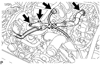 |
Connect the air hose to the air switching valve LH, and install the air tube LH with the 2 bolts.
Connect the vacuum sensor connector and clamp.
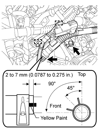 |
Connect the air tube LH to the water inlet housing with the bolt.
Connect the air hose.
Connect the 2 wire harness clamps.
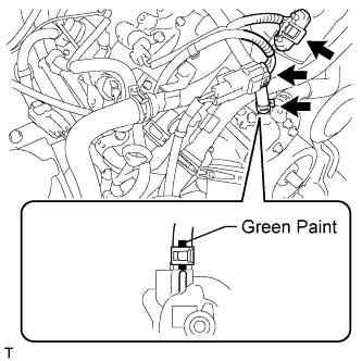 |
Connect the water by-pass hose and 2 connectors.
| 13. INSTALL COWL TOP OUTER PANEL SUB-ASSEMBLY |
Install the outer panel with the 7 bolts.
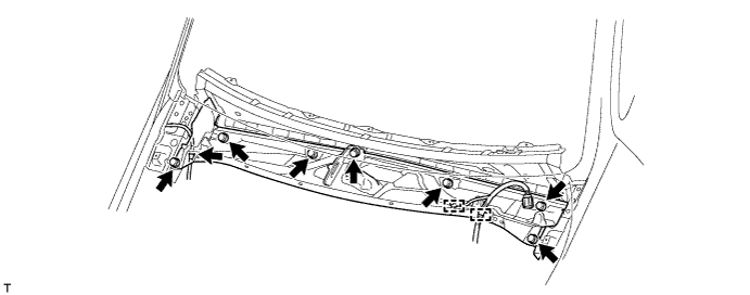
Connect the washer hose.
Connect the 2 wire harness clamps.
| 14. INSTALL FRONT WIPER MOTOR AND LINK ASSEMBLY |
Install the front wiper motor and link (Click here).
| 15. INSTALL EGR VALVE ASSEMBLY |
Install the EGR valve (Click here).
| 16. CHECK FOR FUEL LEAK |
Connect the Techstream to the DLC3.
Turn the ignition switch to ON and Techstream on.
Enter the following menus: Powertrain / Engine and ECT / Active Test / Control the Fuel Pump / Speed.
Check that there are no fuel leaks after doing maintenance anywhere on the fuel system.