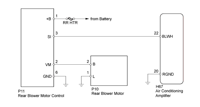
AIR CONDITIONING SYSTEM > Rear Blower Motor Circuit |
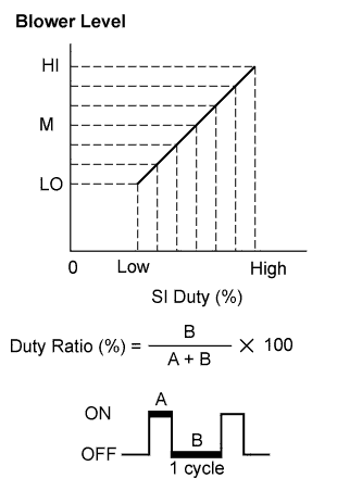
| 1.PERFORM ACTIVE TEST USING TECHSTREAM (REAR BLOWER MOTOR) |
Connect the Techstream to DLC3.
Turn the ignition switch to ON.
Turn the Techstream on.
Enter the following menus: Body Electrical / Air Conditioner / Active Test / Rear Blower Motor
According to the display on the Techstream, check rear blower motor operation while performing the Active Test.
| Tester Display | Test Part | Control Range | Diagnostic Note |
| Rear Blower Motor | Rear blower motor | Min.: 0, Max.: 31 | - |
| Result | Proceed to |
| Rear blower motor operates normally | A |
| Rear blower motor does not operate | B |
| Rear blower motor operates but does not change speed | C |
|
| ||||
|
| ||||
| A | ||
 | ||
| ||
| 2.INSPECT FUSE (RR HTR) |
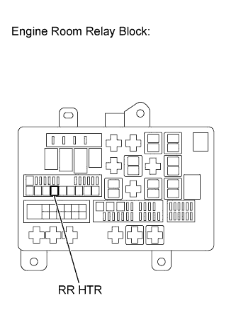 |
Remove the RR HTR fuse from the engine room relay block.
Measure the resistance according to the value(s) in the table below.
| Tester Connection | Condition | Specified Condition |
| RR HTR fuse | Always | Below 1 Ω |
Reinstall the RR HTR fuse.
|
| ||||
| OK | |
 |
| 3.INSPECT REAR BLOWER MOTOR (SYSTEM VOLTAGE) |
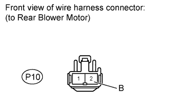 |
Disconnect the P10 rear blower motor connector.
Measure the voltage according to the value(s) in the table below.
| Tester Connection | Condition | Specified Condition |
| P10-2 (B) - Body ground | Always | 11 to 14 V |
Reconnect the rear blower motor connector.
|
| ||||
| OK | |
|
| 4.INSPECT REAR BLOWER MOTOR |
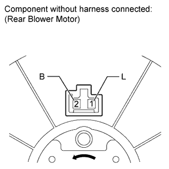 |
Remove rear blower motor (Click here).
Check the rear blower motor.
| Tester Connection | Specified Condition |
| Battery positive (+) → 2 (B) Battery negative (-) → 1 (L) | The rear blower motor operates smoothly. |
Reinstall the rear blower motor.
|
| ||||
| OK | |
|
| 5.CHECK HARNESS AND CONNECTOR (REAR BLOWER MOTOR - REAR BLOWER MOTOR CONTROL, BODY GROUND) |
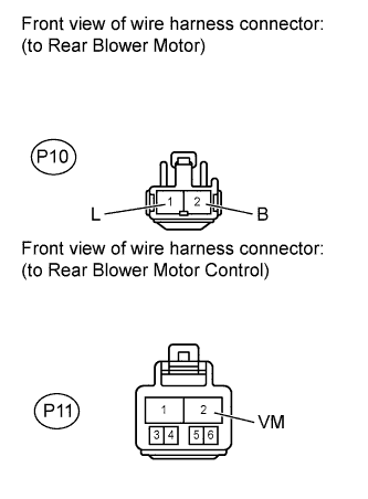 |
Disconnect the P10 rear blower motor connector.
Disconnect the P11 rear blower motor control connector.
Measure the resistance according the value(s) in the table below.
| Tester Connection | Condition | Specified Condition |
| P10-2 (B) - P11-2 (VM) | Always | Below 1 Ω |
| P10-1 (L) - Body ground | Always | Below 1 Ω |
| P10-2 (B) - Body ground | Always | 10 kΩ or higher |
Reconnect the rear blower motor control connector.
Reconnect the rear blower motor connector.
|
| ||||
| OK | |
|
| 6.CHECK HARNESS AND CONNECTOR (REAR BLOWER MOTOR CONTROL - FUSE, BODY GROUND) |
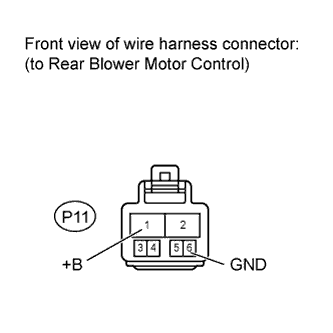 |
Disconnect the P11 rear blower motor control connector.
Measure the resistance and voltage according the value(s) in the table below.
| Tester Connection | Condition | Specified Condition |
| P11-6 (GND) - Body ground | Always | Below 1 Ω |
| Tester Connection | Switch Condition | Specified Condition |
| P11-1 (+B) - Body ground | Ignition switch ON | 11 to 14 V |
Reconnect the rear blower motor control connector.
|
| ||||
| OK | |
|
| 7.CHECK HARNESS AND CONNECTOR (REAR BLOWER MOTOR CONTROL - AIR CONDITIONING AMPLIFIER) |
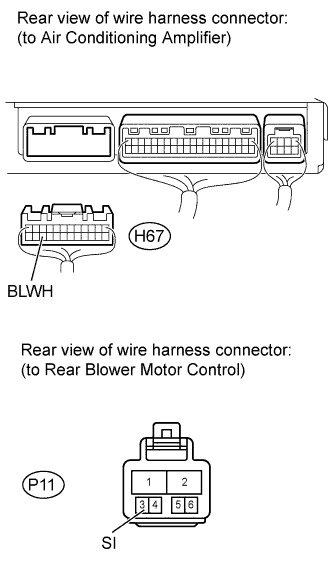 |
Disconnect the P11 rear blower motor control connector.
Disconnect the H67 air conditioning amplifier connector.
Measure the resistance according the value(s) in the table below.
| Tester Connection | Condition | Specified Condition |
| P11-3 (SI)- H67-22 (BLWH) | Always | Below 1 Ω |
| P11-3 (SI) - Body ground | Always | 10 kΩ or higher |
Reconnect the air conditioning amplifier connector.
Reconnect the rear blower motor control connector.
|
| ||||
| OK | |
|
| 8.INSPECT REAR BLOWER MOTOR CONTROL |
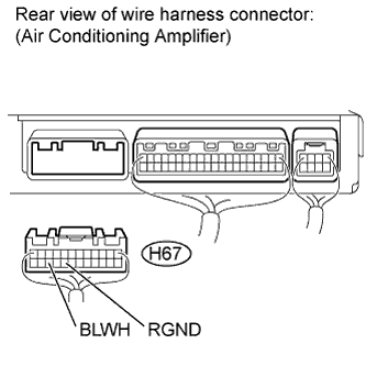 |
Disconnect the H67 air conditioning amplifier connector.
Measure the voltage according the value(s) in the table below.
| Tester Connection | Switch Condition | Specified Condition |
| H67-22 (BLWH) - H67-20 (RGND) | Ignition switch ON Rear blower motor switch OFF | 4.5 to 5.5 V |
Reconnect the air conditioning amplifier connector.
|
| ||||
| OK | |
|
| 9.INSPECT AIR CONDITIONING AMPLIFIER |
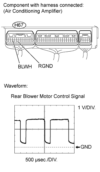 |
Remove the air conditioning amplifier with its connectors still connected (Click here).
Check the waveform of the air conditioning amplifier connector.
| Tester Connection | BLWH - RGND |
| Tool Setting | 1 V/DIV., 500 μsec./DIV. |
| Condition | Ignition switch ON Blower switch LO |
|
| ||||
| OK | ||
| ||
| ||

